Downhole pulsing-shock reach extender system

Active Publication Date: 2018-06-28
PETROSTAR SERVICES LLC
View PDF16 Cites 1 Cited by
  • Summary
  • Abstract
  • Description
  • Claims
  • Application Information

AI Technical Summary

Benefits of technology

[0015]U.S. Pat. No. 8,939,217, issued Jan. 27, 2015 to inventor Jack J. Koll and assignee Tempress Technologies, Inc., covers a “Hydraulic Pulse Valve with Improved Pulse Control.” Hydraulic pulses are produced each time that a pulse valve interrupts the flow of a pressurized fluid through a conduit. The pulse valve includes an elongated housing having an inlet configured to couple the conduit to receive the pressurized fluid, and an outlet configured to couple to one or more tools. In the housing, a valve assembly includes a poppet reciprocating between open and closed positions, and a poppet seat, in which the poppet closes to at least partially block the flow of pressurized fluid through the valve. A pilot within the poppet moves between disparate positions to modify fluid paths within the valve. When the valve is open,

Problems solved by technology

Directional drilling usually involves changes of direction, and each change of direction provides a point of increased drag while diminishing any benefit from downward, insertion force applied at the wellhead.
Because there is likely to be at least some drag all along the surface of the deployed tubing, a longer, or deeper, run will encounter, increasing total drag.
Very deep coiled-tubing operations therefore encounter increased drag, or static friction, which eventually cannot be

Method used


Image

  • Downhole pulsing-shock reach extender system
  • Downhole pulsing-shock reach extender system
  • Downhole pulsing-shock reach extender system

Examples


Embodiment Construction

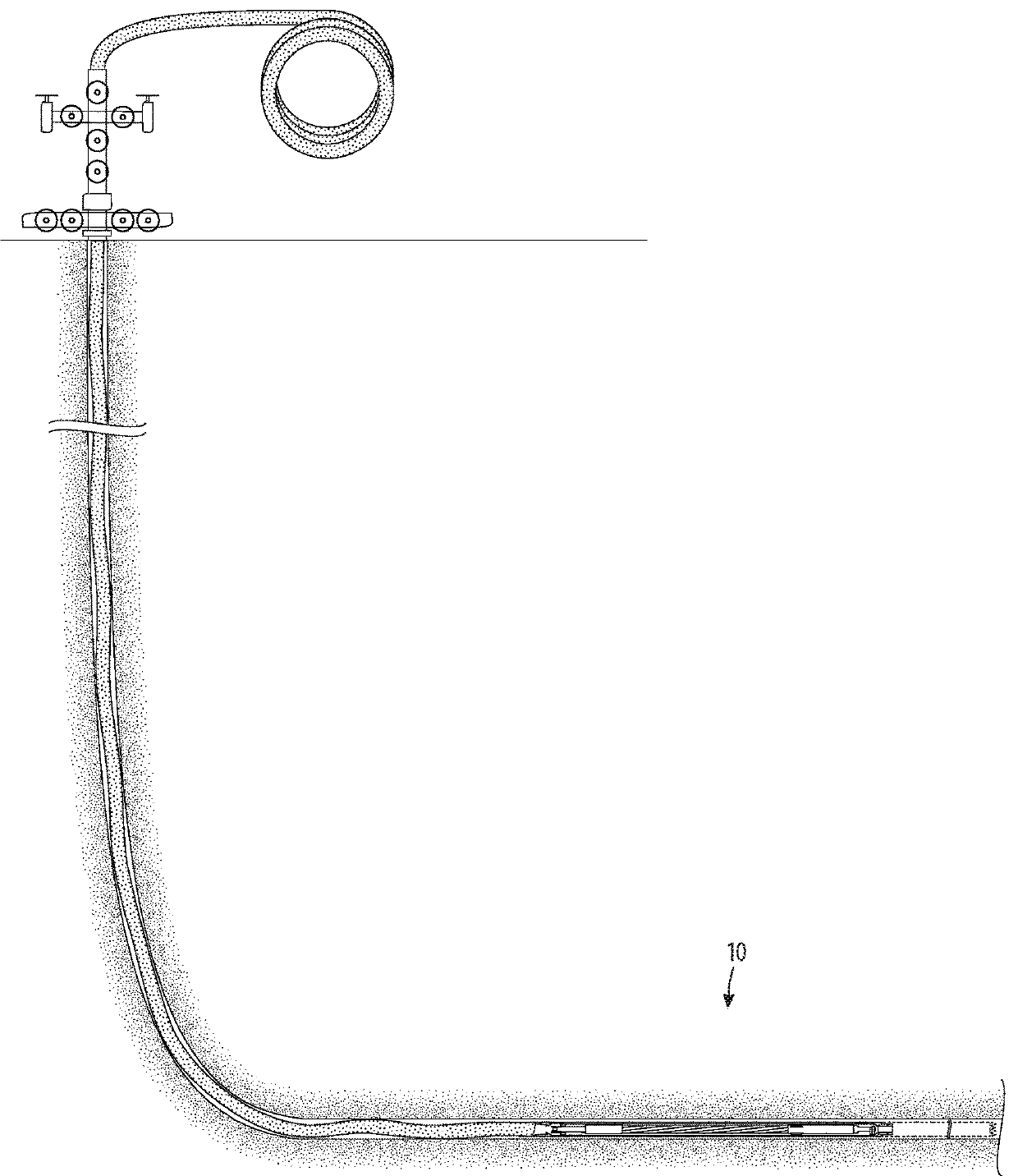
[0025]Referring to FIG. 1, the downhole pulsing-shock reach extender 10 of the invention is shown schematically, in use in coiled-tubing, directional drilling, downhole operations.

[0026]The downhole pulsing-shock reach extender 10 assists significantly in overcoming the static friction encountered in deep directional-drilling downhole coiled-tubing operations by generating pulsed hydraulic shocks, which are a pulsation of energy at the workstring, by creating a fluid-hammer condition using an essentially constant or slowly changing normal drilling-fluid pressure which will not damage other components of the workstring, thereby extending the depth limit of downhole operations.

[0027]The downhole pulsing-shock reach extender 10 generates a force, during a small window of time, that is able to work as intended before being dispersed, in a continuing cycle. No pulsation from the wellhead can effectively reach the workstring. Moreover, the application of an extreme amount of pressure will...


PUM


Abstract

A downhole pulsing-shock reach extender apparatus for overcoming static friction resistance in coiled-tubing drilling-fluid-pressure driven downhole operations, generating pulsed hydraulic shocks at the workstring by creating a fluid-hammer condition by repeated sudden opening and closing of a valve controlling a diverted portion of the flow of drilling fluid, while maintaining a constant flow of a portion of drilling fluid sufficient to operate and prevent damage to other components of the workstring, thereby extending the depth limit of downhole operations.

Description

CROSS-REFERENCE TO RELATED APPLICATIONS[0001]This application is a continuation-in-part of my co-pending application Ser. No. 15 / 428,792, filed Feb. 9, 2017 for a “Downhole Fluid-Pressure Safety Bypass Apparatus,” which is a continuation-in-part of my application Ser. No. 15 / 392,846, filed Dec. 28, 2016 for a “Downhole Pulsing Shock-Reach Extender System,” currently pending, the full disclosures of which are incorporated by reference herein and priority of which is hereby claimed.BACKGROUND[0002]This invention is a downhole pulsing-shock reach extender apparatus for overcoming static friction resistance in coiled-tubing drilling-fluid-pressure driven downhole operations.[0003]Drilling, in its broad sense, includes not only the initial drilling of a hole, but many subsequent trips down the hole for workover and inspection. Where older methods of drilling use sections of rigid pipe threaded together, coiled-tubing drilling uses a somewhat flexible, continuous tube that can be spooled ...

Claims


Application Information

Patent Timeline
IPC IPC(8): E21B28/00E21B34/14
CPCE21B28/00E21B34/14E21B7/046E21B4/02
Inventor MESSA, RICHARDGASSER, CHRISTOPHERGUILBEAUX, BRADYROCHON, ASHLEY
Owner PETROSTAR SERVICES LLC
Why Eureka
Try Eureka