Nasal cavity dilator

a dilator and nasal cavity technology, applied in the field of dilators, can solve the problems of bringing more pain to patients, unable to fundamentally cure the deformation of the nasal cavity, and high cost of operation, and achieves low expansion strength, good dilating ability, and low adaptability to nares.

Active Publication Date: 2018-07-05
WANG LEI
View PDF1 Cites 1 Cited by
  • Summary
  • Abstract
  • Description
  • Claims
  • Application Information

AI Technical Summary

Benefits of technology

[0007]The object of the present invention is to solve the technical problem existing in current nasal dilators, such as low expansion strength, low adaptability to nares of different shapes, and so on, which is caused by structural limitation. Provided is a nasal dil...

Problems solved by technology

However, the cost of the operation is usually high and cannot fundamentally cure the deformation of the nasal passage.
Moreover, the removal of turbinate can cause “empty nose syndrome” and other sequelae, which will bring more pain to the patients.
The disadvantage of...

Method used


Image

  • Nasal cavity dilator
  • Nasal cavity dilator
  • Nasal cavity dilator

Examples


Embodiment Construction

[0034]The nasal dilator of the present invention will be illustrated in detail hereinafter by incorporating the drawings and the embodiments.

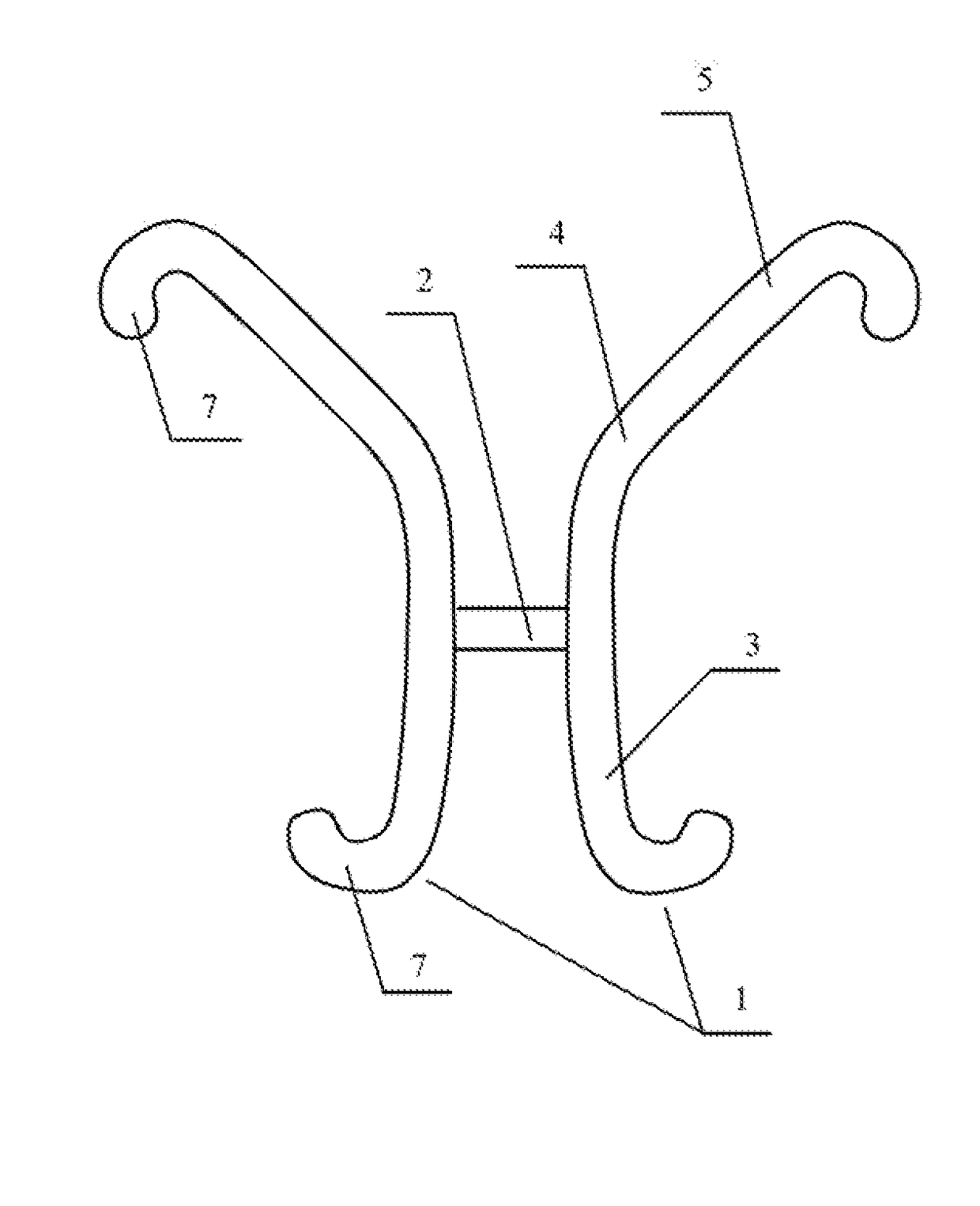
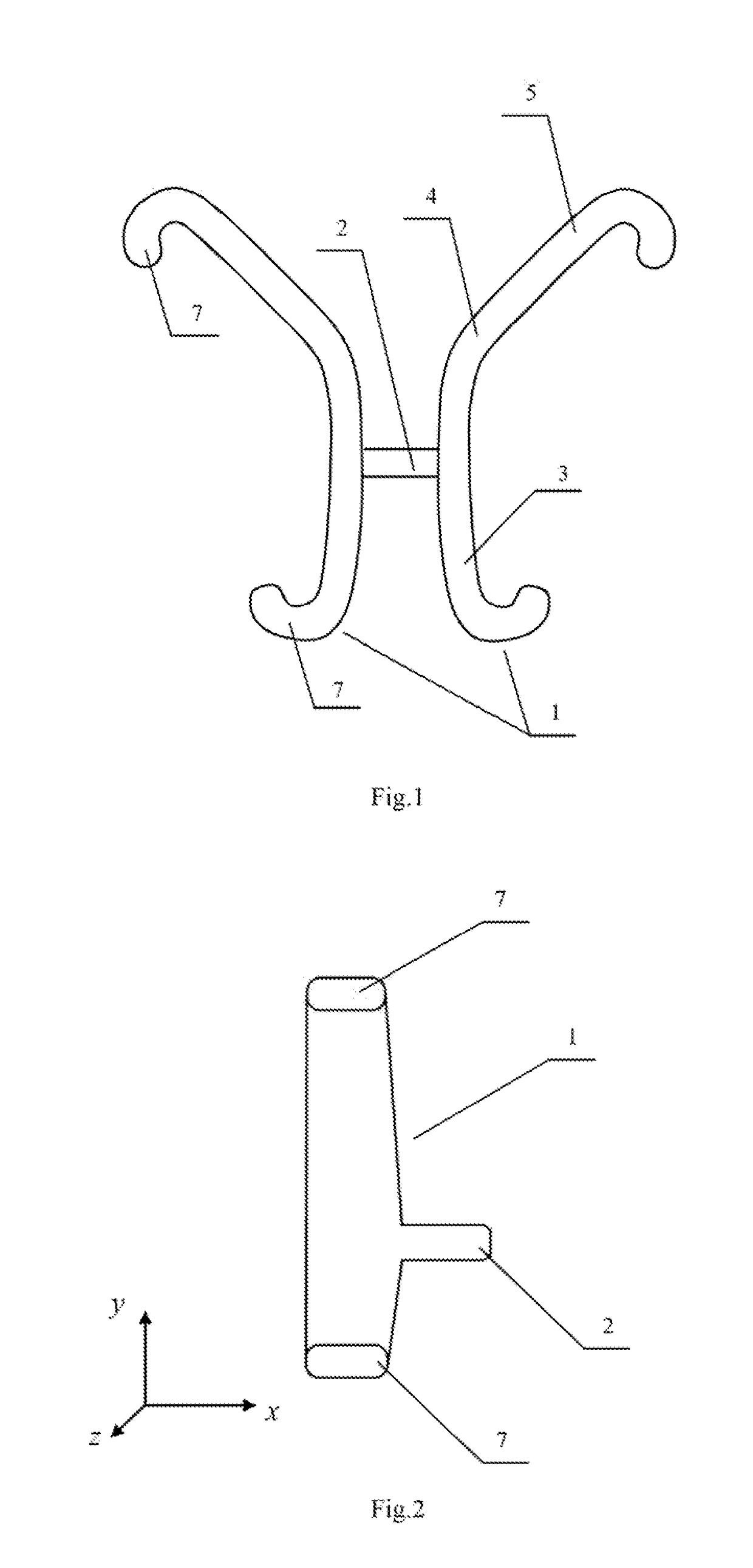
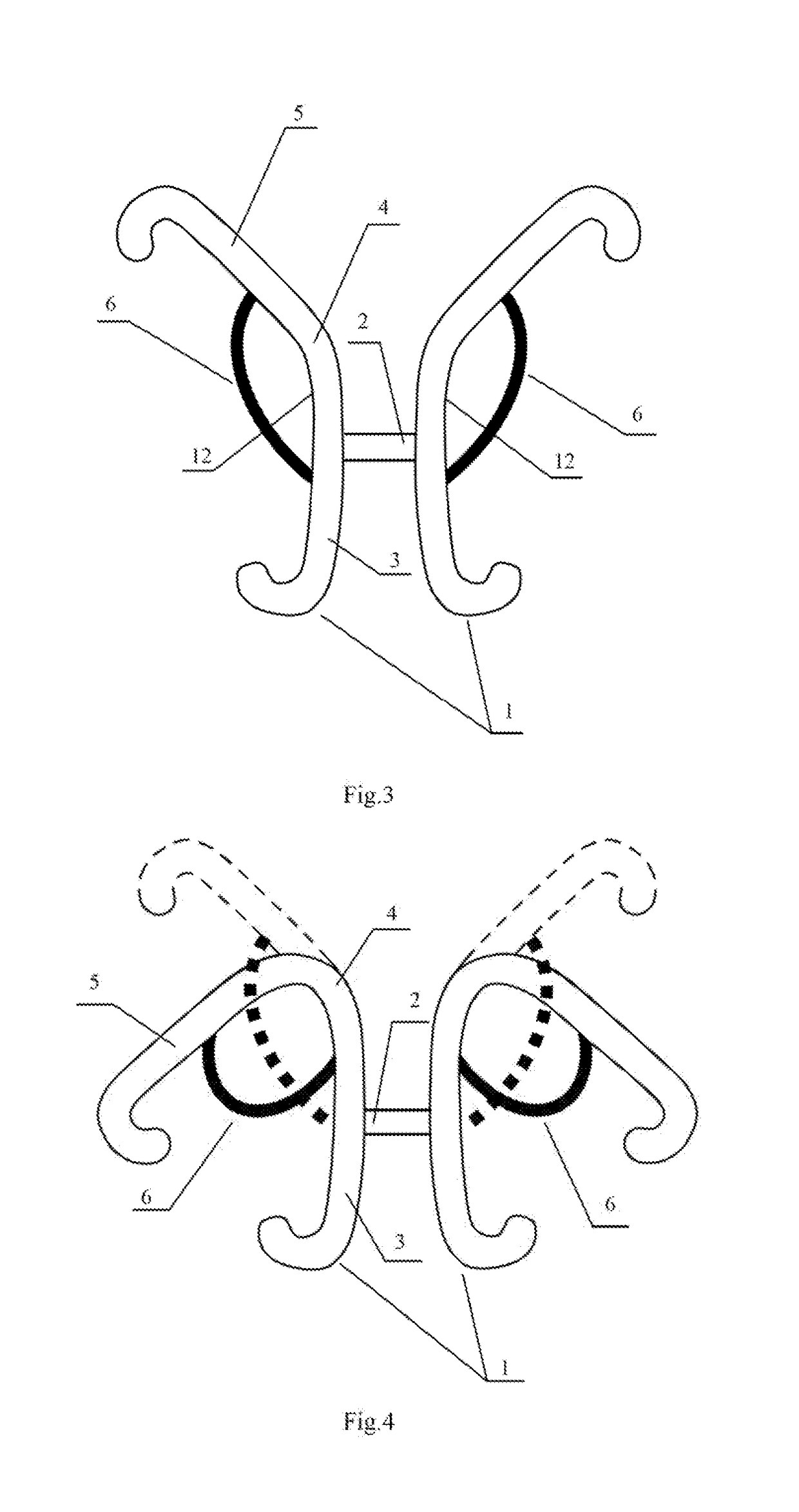
[0035]As shown in FIG. 1, the nasal dilator provided by the present invention includes two intranasal stents 1 and connecting band 2. Two intranasal stents 1 are symmetrically connected to two ends of connecting band 2 to form an integral whole. In use, two intranasal stents 1 are further bent respectively and then inserted into two nares of a user. The rebound ability of intranasal stents 1 is utilized to dilate passages of the nasal cavities near the nasal valve area so as to improve the efficiency of ventilation of the nasal cavities. Two ends of connecting band 2 enter the nasal cavities together with intranasal stents 1. A middle part of connecting band 2 is positioned across the nasal septum and exposed outside the nose. The user can remove the nasal dilator by pulling connecting band 2 outwardly.

[0036]Nasal stent 1 is made of elastic mat...


PUM


Abstract

The present invention provides a nasal dilator including: two intranasal stents (1) and a connecting band (2), wherein each of two ends of the connecting band (2) being symmetrically connected to one intranasal stent (1), each intranasal stent (1) having an elastic band-shape structure, each intranasal stent (1) has a straight-line shape, an arc-line shape, a bow shape, or a fold-line shape in a cross section perpendicular to a width direction of the elastic banded structure, each intranasal stent (1), along a length direction of the elastic band-shape structure, comprises: a nasal septum supporting section (3), a bending section (4), and a nasal alar dilating section (5), each intranasal stent (1) has a generally C-shape in a cross-section perpendicular to a central axis of nasal passages, wherein an opening of the C-shape faces towards a nasal base (11).

Description

CROSS REFERENCE TO RELATED APPLICATIONS[0001]This application is the national phase entry of International Application No. PCT / CN2016 / 084306, filed on Jun. 1, 2016, the entire contents of which are incorporated herein by reference.TECHNICAL FIELD[0002]The present invention relates to the field of dilating device, especially to a nasal cavity dilator.BACKGROUND[0003]Currently, a considerable number of people are suffering from nasal obstruction disease (also known as rhinobyon). The narrowest part of the nasal cavity of the human body is the nasal valve area (intranasal hole). This nasal valve area is located in the deep part of the nasal vestibule and in front of the front-end of the inferior nasal concha. It is a long and narrow triangular region and is a part where the greatest nasal resistance exists. The nasal obstruction normally occurs in the nasal valve area and the front-end of the inferior nasal concha adjacent to the nasal valve area. Normally, the nasal obstruction is cau...

Claims


Application Information

Patent Timeline
IPC IPC(8): A61F5/08
CPCA61F5/08A61M29/02
Inventor WANG, LEI
Owner WANG LEI
Why Eureka
Try Eureka