Method for determining a tread depth of a tire profile and control device therefor

a technology of tire profile and control device, which is applied in the direction of measurement device, vehicle components, instruments, etc., can solve the problem of high accuracy in determining the profile depth, and achieve the effect of high reliability and high accuracy

Active Publication Date: 2018-07-05
CONTINENTAL REIFEN DEUTSCHLAND GMBH
View PDF6 Cites 12 Cited by
  • Summary
  • Abstract
  • Description
  • Claims
  • Application Information

AI Technical Summary

Benefits of technology

[0004]It is an object of the invention to provide a method for determining a profile depth of a tire profi...

Problems solved by technology

A disadvantage of previous evaluation methods is that the determination of the profile depth is highly...

Method used


Image

  • Method for determining a tread depth of a tire profile and control device therefor
  • Method for determining a tread depth of a tire profile and control device therefor
  • Method for determining a tread depth of a tire profile and control device therefor

Examples


second embodiment

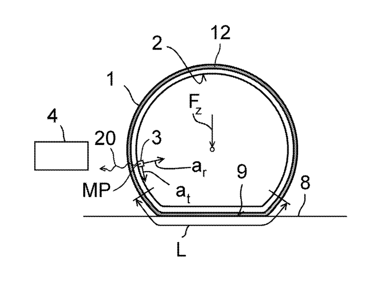
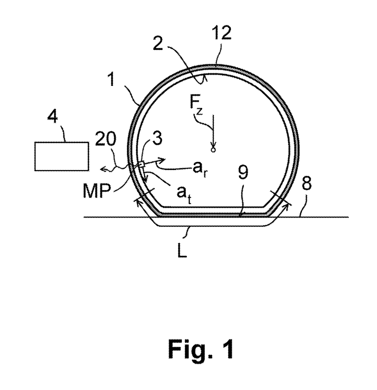
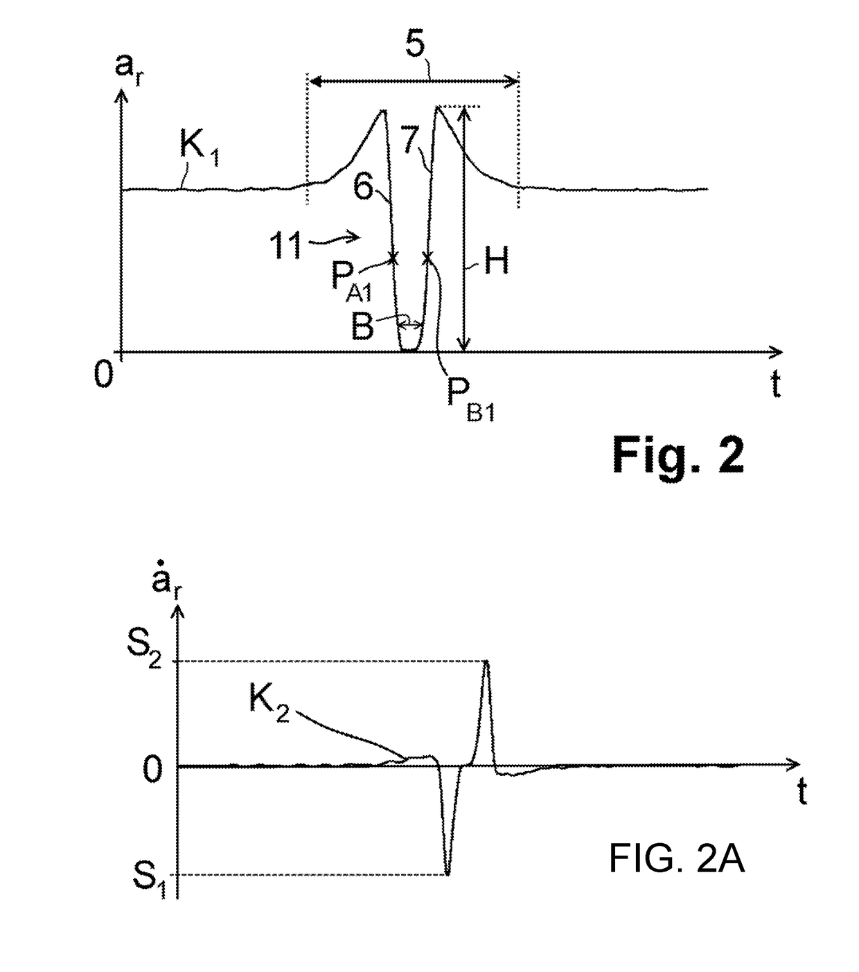
[0045]In a first and second embodiment, shown in FIGS. 2, 2A and 2B, firstly the radial acceleration ar is observed. In this regard, by way of example, FIG. 2 illustrates a characteristic curve K1 in which the radial acceleration ar measured by the tire sensor module 3 is plotted versus the time t. Outside an observation window 5, the radial acceleration ar is approximately constant. Within the observation window 5, the radial acceleration ar initially rises to a high point, then has a falling flank 6 which hereafter falls approximately to zero and subsequently transitions into a rising flank 7, which rises up to a second high point. At greater time values t, the radial acceleration ar falls again to a constant value outside the observation window 5, wherein the exact profile is dependent on the orientation of the tire sensor module 3 within the vehicle tire 1. Thus, in this example, the observation window 5 corresponds to a tire contact patch region L, in which a curvature of the t...

first embodiment

[0047]In a first embodiment, for the determination of a profile depth D of the vehicle tire 1, firstly a maximum negative gradient S1 and / or a maximum positive gradient S2 of the characteristic curve K1 within the observation window 5 is determined, wherein the maximum negative gradient S1 is assigned to the falling flank 6 and the maximum positive gradient S2 is assigned to the rising flank 7. It is then preferably possible to form a derivative K2 of the characteristic curve K1 with respect to the time t, which derivative is illustrated in FIG. 2A. An ordinate value (y value) of a low point and of a high point of the derivative K2 then yields the maximum negative gradient S1 and the maximum positive gradient S2 respectively.

[0048]For the further evaluation, that point of the characteristic curve K1 which is assigned the lowest ordinate value in the derivative K2 is selected as a first observation point PA1, and / or that point of the characteristic curve K1 which is assigned the high...


PUM


Abstract

A method is for determining a profile depth of a tire profile. The method includes at least the following steps: a) detecting an acceleration of a measurement point on a tire inner side of a vehicle tire, wherein a deviation, caused by contact of the vehicle tire with a roadway, of the acceleration of the measurement point within an observation window is detected, b) deriving at least one analytical characteristic variable which is characteristic of the profile of the detected acceleration, wherein the at least one analytical characteristic variable characterizes the non-periodic profile of the detected acceleration within one tire rotation, c) determining the profile depth in a manner dependent on the at least one analytical characteristic variable, wherein a calibration curve yields the dependency between the analytical characteristic variable and the profile depth, and the calibration curve assigns a profile depth to the derived analytical characteristic variable.

Description

CROSS REFERENCE TO RELATED APPLICATIONS[0001]This application is a continuation application of international patent application PCT / EP2016 / 060625, filed May 12, 2016, designating the United States and claiming priority from German application 10 2015 216 212.5, filed Aug. 25, 2015, and the entire content of both applications is incorporated herein by reference.FIELD OF THE INVENTION[0002]The invention relates to a method for determining a profile depth of a tire profile, and to a control unit for carrying out the method.BACKGROUND OF THE INVENTION[0003]It is known for a tire sensor module to be arranged on a tire inner side of a vehicle tire, which tire sensor module can determine characteristic variables of the vehicle tire, for example a tire pressure or a tire temperature, and can transmit these via a radio signal to a control unit. Furthermore, a tire sensor module of the type can also detect an acceleration, wherein, in particular, a radial acceleration of the tire inner side c...

Claims


Application Information

Patent Timeline
IPC IPC(8): G01B21/18G01M17/02G01B21/20
CPCG01B21/18G01M17/02G01B21/20B60C11/246B60C2019/004
Inventor CYLLIK, ADRIANHAHN, CARSTENLEHN, MICHAELVOLK, HEINERWELSER, JOACHIMNEUBER, CORD-CHRISTIANHUYNH, JENNY
Owner CONTINENTAL REIFEN DEUTSCHLAND GMBH
Why Eureka
Try Eureka