
Apparatus and method for diagnosing failure of switch element

a technology of switch element and apparatus, which is applied in the direction of power supply testing, relays, instruments, etc., can solve the problems of short circuit failure, open circuit failure, and the external connection of the battery not being appropriately controlled, so as to reduce the cost of a diagnosis apparatus and accurately diagnose the problem.

Active Publication Date: 2018-07-05
LG ENERGY SOLUTION LTD
View PDF1 Cites 23 Cited by
  • Summary
  • Abstract
  • Description
  • Claims
  • Application Information

AI Technical Summary

Benefits of technology

The present invention relates to a method for diagnosing failures in a switch element used for external connection of a battery. The method can detect switch element failures regardless of the voltage level applied to the battery's external terminal. The invention also suggests using a sensor element that measures the battery's charge or discharge current to detect switch element failures, reducing the cost of the diagnosis apparatus. Additionally, the invention can accurately diagnose weak short circuit failures in the switch element. The invention may also be useful for parallel power systems connecting multiple batteries in parallel.

Problems solved by technology

When the switch element has a failure, the external connection of the battery may not be appropriately controlled.
The short circuit failure refers to a failure in which the switch element is constantly maintained in a turn-on state irrespective of the control signal.
On the other hand, the open circuit failure refers to a failure in which the switch element is constantly maintained in a turn-off state irrespective of the control signal.
Among the above-described failures of the switch element, the short circuit failure is more serious.
The short circuit failure results from various causes.
For example, in a mechanical switch element such as a relay, a short circuit failure may occur when contact points are fused thereby to be in contact with each other.
As another example, in a semiconductor switch such as a solid state relay (SSR), a short circuit failure may occur when insulation is permanently broken because characteristics of a semiconductor material deteriorate and thus a threshold voltage is excessively lowered.
The short circuit failure causes overcharge or overdischarge of the battery.
The overcharge and overdischarge not only deteriorate performance of the battery but also cause overheating and, in a worse case, explosion of the battery.
That is, although a turn-off control signal is applied to the switch element, if the voltage between the two terminal ends of the switch element is close to zero, it may be diagnosed that the switch element has a short circuit failure.
Consequently, even when the switch element does not have a short circuit failure, it may be incorrectly diagnosed that a short circuit failure has occurred.

Method used


Image

  • Apparatus and method for diagnosing failure of switch element
  • Apparatus and method for diagnosing failure of switch element
  • Apparatus and method for diagnosing failure of switch element

Examples


Embodiment Construction

[0048]Hereinafter, preferred embodiments of the present disclosure will be described in detail with reference to the accompanying drawings. Prior to the description, it should be understood that the terms used in the specification and the appended claims should not be construed as limited to general and dictionary meanings, but interpreted based on the meanings and concepts corresponding to technical aspects of the present disclosure on the basis of the principle that the inventor is allowed to define terms appropriately for the best explanation. Therefore, the description proposed herein is just a preferable example for the purpose of illustrations only, not intended to limit the scope of the disclosure, so it should be understood that other equivalents and modifications could be made thereto without departing from the scope of the disclosure.

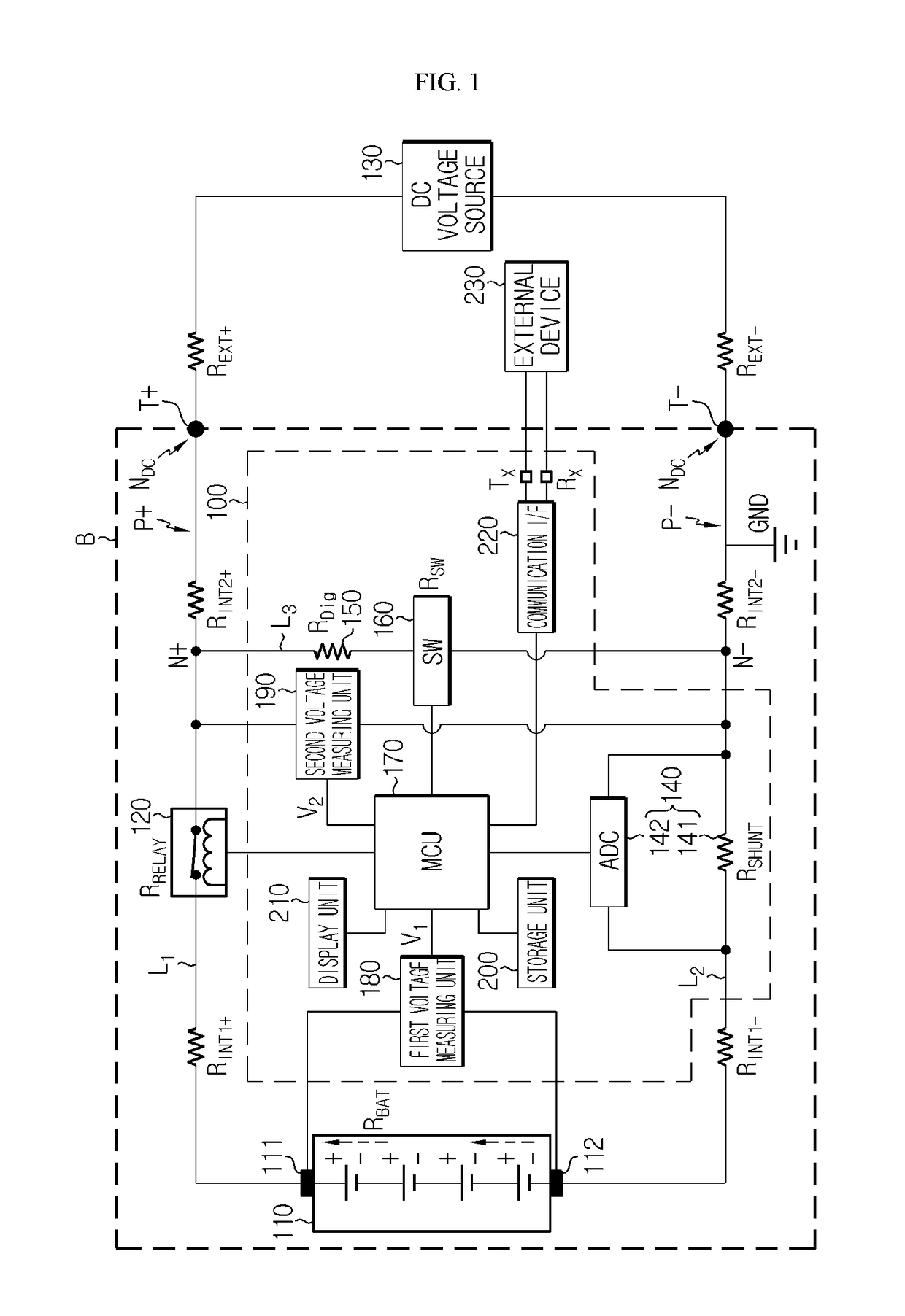
[0049]FIG. 1 is a structural view of an apparatus 100 for diagnosing a failure of a switch element 120, according to an embodiment of the pre...


PUM


Abstract

Disclosed are an apparatus and method of diagnosing a failure of a switch element used to switch on or off external connection of a battery. The apparatus according to the present disclosure is an apparatus for diagnosing a failure of a switch element provided on a first line between a first electrode of a battery and a first external terminal, the apparatus including a current measuring unit configured to measure a current flowing through a second line between a second electrode of the battery and a second external terminal, a diagnosis resistor and a diagnosis switch provided on a third line to connect an outer node of the switch element and an outer node of the current measuring unit, and connected to each other in series, and a controller configured to apply a control signal for turning on or off the switch element, to the switch element, to turn on the diagnosis switch after the control signal is applied and then receive a measured current value from the current measuring unit, to determine a level of the current flowing through the second line, by using the measured current value, and to diagnose a failure of the switch element by comparing the current level to a reference current level.

Description

TECHNICAL FIELD[0001]The present disclosure relates to an apparatus and method of diagnosing a failure of a switch element used to turn on or off external connection of a battery.[0002]The present application claims priority to Korean Patent Application No. 10-2016-0019936 filed on Feb. 19, 2016 in the Republic of Korea, the disclosure of which is incorporated herein by reference.BACKGROUND ART[0003]Batteries are rapidly popularized not only in mobile devices (e.g., mobile phones, laptop computers, smartphones, and smartpads) but also in electricity-driven vehicles (e.g., electric vehicles (EVs), hybrid electric vehicles (HEV), and plug-in hybrid electric vehicles (PHEVs)), high-capacity energy storage systems (ESSs), etc.[0004]A battery is connected to an external power line through a switch element. The switch element is turned on or off by a control signal.[0005]When the switch element is turned on, charge or discharge of the battery is enabled in association with the power line....

Claims


Application Information

Patent Timeline
IPC IPC(8): G01R31/327G01R19/165G01R31/36G01R31/02G01R31/50
CPCG01R31/3278G01R19/16504G01R19/16571G01R31/3696G01R31/025G01R31/026G08C19/02G01R31/40G01R19/16542H01H47/002G01R31/50G01R31/364
Inventor HUH, GEUN-HOELEE, JONG-CHEOL
Owner LG ENERGY SOLUTION LTD
Learn More