Compact confocal dental scanning apparatus

a confocal and dental scanning technology, applied in the field of three-dimensional (3d) scanning apparatuses and methods of objects, can solve the problems of general bulkiness, difficulty in use, and inconvenience, and achieve the effects of reducing the number of lenses, simple transparency, and reducing the noise of speckles

Active Publication Date: 2018-07-12
ALIGN TECH
View PDF1 Cites 68 Cited by
  • Summary
  • Abstract
  • Description
  • Claims
  • Application Information

AI Technical Summary

Benefits of technology

[0020]As mentioned above, described herein are handheld apparatuses for confocal (three-dimensional) scanning. These apparatuses (devices, systems, etc.) may be compact and lightweight, and may include an LED based emitter providing a reduced speckle noise. These apparatuses may also be used without requiring precise alignment (pre-alignment) as needed in other systems in which an array of light spots is used to provide confocal imaging, having a maximal alignment error that is about 0.5 micrometers or less. The confocal apparatuses described herein may be operated without the need for such precise alignment, by using a continuous pattern instead of spots array. As described herein a simple transparency may replace the spot array used in other systems. In general, these apparatuses may require substantially fewer

Problems solved by technology

Other surface topology scanners have been described, but are generally rel

Method used


Image

  • Compact confocal dental scanning apparatus
  • Compact confocal dental scanning apparatus
  • Compact confocal dental scanning apparatus

Examples


Embodiment Construction

[0056]The present disclosure now will be described in detail with reference to the accompanying figures. This disclosure may be embodied in many different forms and should not be construed as limited to the example embodiments discussed herein.

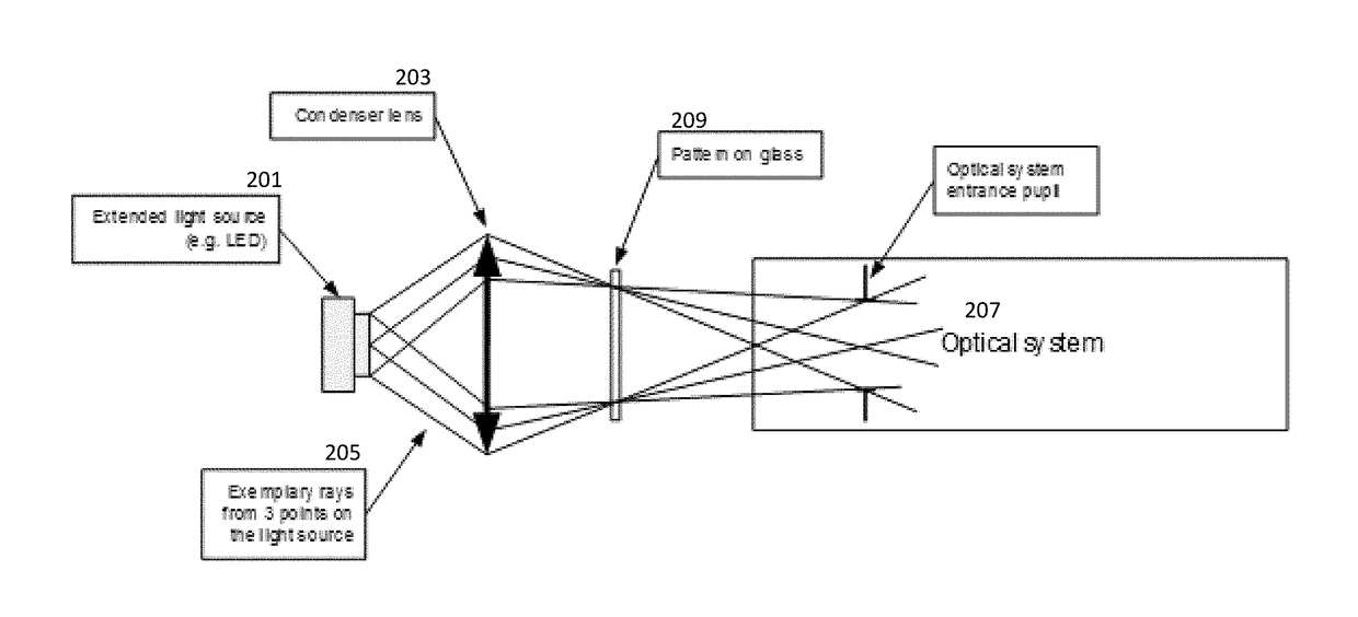
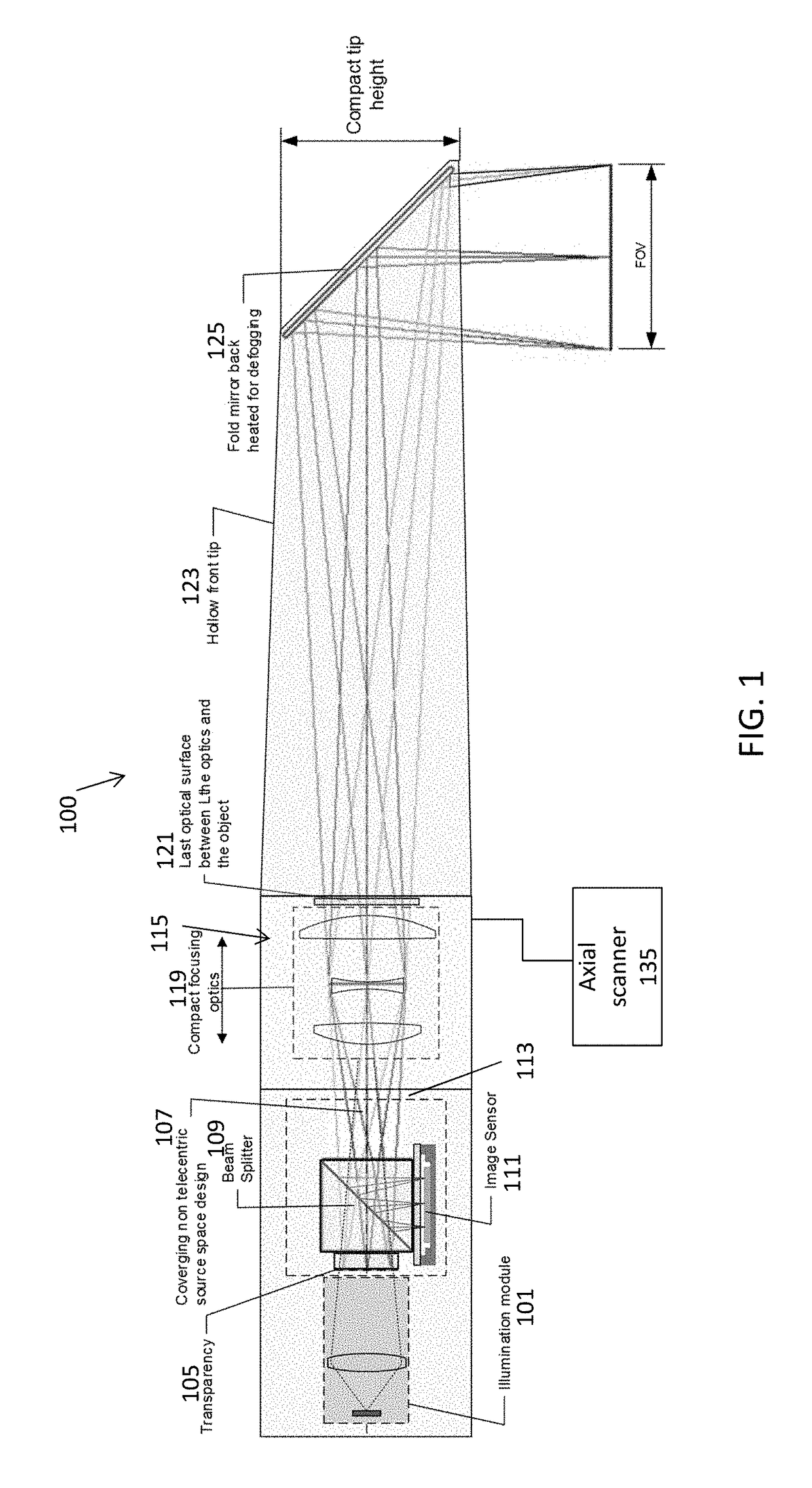
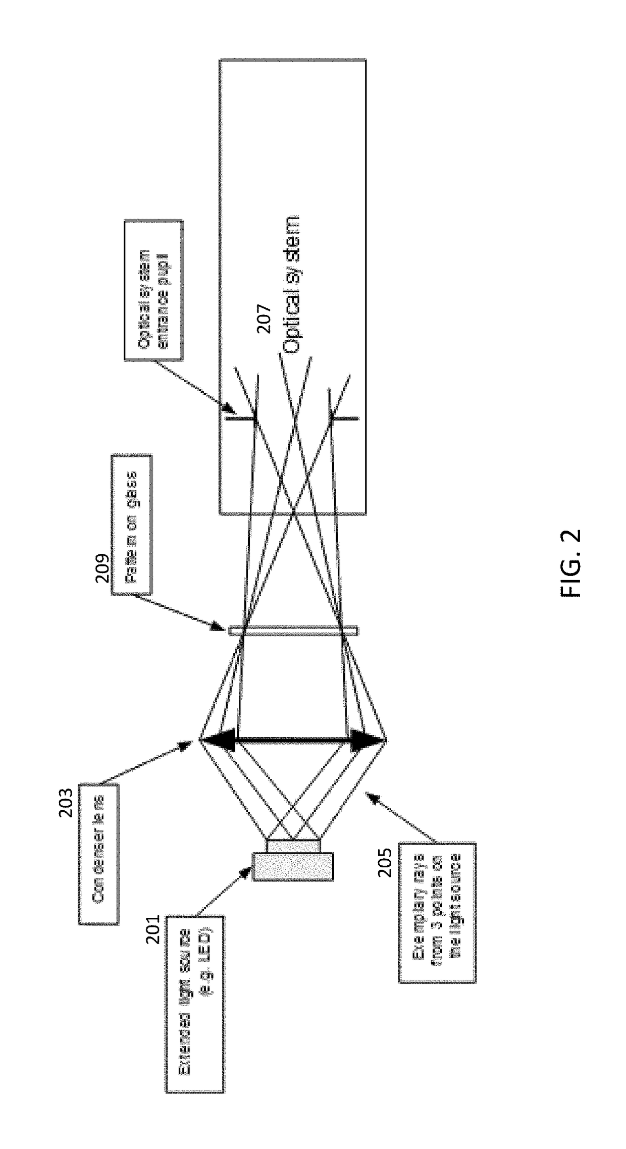
[0057]Described herein are compact apparatuses for confocal 3D scanning. These apparatuses can include confocal illuminator configured to generate confocal illumination to an object. The confocal illuminator can comprise a spatial pattern disposed on a transparent base (transparency) and a light source configured to provide illumination of the spatial pattern so that it can be projected onto an object. The apparatus can comprise an optical system (including projection / imaging optics) comprising one or more lenses and having an optical axis. The apparatus may also include illumination optics for illuminating a pattern / transparency forming the spatial pattern. The apparatus can comprise an axial scanner (e.g., a depth scanning module) that is co...


PUM


Abstract

Described herein are apparatuses and methods for confocal 3D scanning. The apparatus can comprise a spatial pattern disposed on a transparent base and a light source configured to provide illumination to the spatial pattern and an optical system comprising projection/imaging optics having one or more lenses and an optical axis. The projecting/imaging optics may be scanned to provide depth scanning by moving along the optical axis.

Description

CROSS REFERENCE TO RELATED APPLICATIONS[0001]This patent application claims priority to U.S. provisional patent application No. 62 / 445,663, filed Jan. 12, 2017, and titled “COMPACT CONFOCAL DENTAL SCANNING APPARATUS,” which is herein incorporated by reference in its entirety.[0002]The following U.S. patent applications are herein incorporated by reference in their entirety to the same extent as if each individual publication or patent application was specifically and individually indicated to be incorporated by reference: U.S. patent application Ser. No. 14 / 741,172, titled “APPARATUS FOR DENTAL CONFOCAL IMAGING,” filed on Jun. 16, 2015, and U.S. patent application Ser. No. 14 / 825,173, titled “CONFOCAL IMAGING APPARATUS WITH CURVED FOCAL SURFACE,” filed on Aug. 13, 2015.INCORPORATION BY REFERENCE[0003]All publications and patent applications mentioned in this specification are herein incorporated by reference in their entirety to the same extent as if each individual publication or p...

Claims


Application Information

Patent Timeline
IPC IPC(8): A61B5/00A61C7/00G01B11/24G02B21/00
CPCA61B5/0068A61B5/0088A61C7/002G01B11/24G02B21/0024A61C19/04A61C9/006A61B5/7246A61C9/0066A61B1/247G02B21/0028G02B21/367G01B11/0608
Inventor ATIYA, YOSSEFVERKER, TAL
Owner ALIGN TECH
Why Eureka
Try Eureka