Method for converting heavy hydrocarbon feedstocks

a technology of hydrocarbon feedstock and conversion method, which is applied in the direction of hydrocarbon oil cracking, metal/metal-oxide/metal-hydroxide catalyst, physical/chemical process catalyst, etc., can solve the problems of clogging process equipment, affecting the stability of the effluent, and relatively difficult upgrading of oil residues, so as to increase the thermal cracking of the heavy cut, improve the stability of the effluent, and increase the conversion

Inactive Publication Date: 2018-07-12
INST FR DU PETROLE
View PDF6 Cites 4 Cited by
  • Summary
  • Abstract
  • Description
  • Claims
  • Application Information

AI Technical Summary

Benefits of technology

[0006]One of the aims of the invention is to provide a process layout for a hydroconversion process which can be used to improve the stability of the effluents for a given level of conversion of the heavy cuts, and also to increase the conversion compared with conventional hydroconversion processes.
[0007]Conventional process layouts for the hydroconversion of residues such as those described in U.S. Pat. No. 4,521,295, U.S. Pat. No. 4,495,060 or U.S. Pat. No. 4,457,831 recommend operating at hourly space velocities (HSV) or space velocities (volume flow rate of feed with respect to the reaction volume) in the range 0.1 to 2.5 h−1, temperatures in the range 300-500° C. and partial pressures of hydrogen in the range 1000 to 5000 psig. In these process layouts, the temperature remains the key parameter for controlling the level of conversion of the heavy cuts. For a high conversion operation, a high temperature is thus recommended in order to increase thermal cracking of the heavy cuts. In this configuration, the maximum level of conversion allowing appropriate operation of an industrial unit will always be limited by the formation of sediments. In fact, the temperature increases the condensation / polymerization reaction kinetics more rapidly than that for hydrogenation reactions, thus bringing about secondary and unwanted reactions which are responsible for the formation of sediments and coke precursors.
[0008]In order to overcome this limit of operability of the hydroconversion units, conventional process layouts for the conversion of residues in the prior art can incorporate supplemental steps such as deasphalting in order to obtain high levels of conversion for a reduced severity. This is the case with the concept described in patents US 2008 / 0083652, U.S. Pat. No. 7,214,308 and U.S. Pat. No. 5,980,730. In fact, in residue hydroconversion process layouts combining a deasphalting unit with a fixed bed, moving bed, ebullated bed and / or entrained slurry bed hydroconversion unit, the deasphalting unit may be positioned upstream via an indirect route such as, for example, in patent U.S. Pat. No. 7,214,308, or downstream of the hydroconversion process via a direct route such as, for example, in patents FR 2 776 297 and U.S. Pat. No. 5,980,730. The patents FR 2 776 297, U.S. Pat. No. 5,980,730 and U.S. Pat. No. 7,214,308 describe these two possible types of conversion process layout in detail.
[0009]A process layout for the hydroconversion of residues generally associates two principal unitary steps in succession: a hydroconversion step and a deasphalting step, with an intermediate atmospheric distillation step and optionally an intermediate vacuum distillation step being carried out between these two unitary steps. In general, recycles of deasphalted oil (DAO) to the hydroconversion step may be employed in this type of process layout.
[0010]The greatest limitations to this type of process layout are the quantity of asphalt produced, which is difficult to upgrade; recycling the DAO cut to the inlet to the hydroconversion zone, which demands a substantial increase in the volume of the reaction zones as well as the separation zones (as described in patents US 2012 / 061292A and WO 14096591A1) increases the investment required and the operating costs compared with a process without DAO recycling.
[0011]Fluxes such as aromatic cuts, non-exhaustive examples of which that may be cited including LCO (light cycle oil), HCO (heavy cycle oil) obtained from the fluid catalytic cracking process, may be used in order to stabilize the effluents from residue hydroconversion units. However, their use has a major impact on the yield of the process because the cost of these cuts and their use results in an increase in the size of the units. In addition, these stabilizing cuts are not always available on site and their use is necessarily to the detriment of the production of an upgradeable cut. This set of reasons explains why the use of a stabilizing cut is very limited.

Problems solved by technology

These oil residues are relatively difficult to upgrade.
The excessive presence of these products then results in deactivation of the catalyst, and leads to clogging of the equipment of the process, and in particular in the separation and distillation equipment.
In this configuration, the maximum level of conversion allowing appropriate operation of an industrial unit will always be limited by the formation of sediments.
In fact, the temperature increases the condensation / polymerization reaction kinetics more rapidly than that for hydrogenation reactions, thus bringing about secondary and unwanted reactions which are responsible for the formation of sediments and coke precursors.
The greatest limitations to this type of process layout are the quantity of asphalt produced, which is difficult to upgrade; recycling the DAO cut to the inlet to the hydroconversion zone, which demands a substantial increase in the volume of the reaction zones as well as the separation zones (as described in patents US 2012 / 061292A and WO 14096591A1) increases the investment required and the operating costs compared with a process without DAO recycling.
However, their use has a major impact on the yield of the process because the cost of these cuts and their use results in an increase in the size of the units.
In addition, these stabilizing cuts are not always available on site and their use is necessarily to the detriment of the production of an upgradeable cut.
This set of reasons explains why the use of a stabilizing cut is very limited.

Method used


Image

  • Method for converting heavy hydrocarbon feedstocks
  • Method for converting heavy hydrocarbon feedstocks
  • Method for converting heavy hydrocarbon feedstocks

Examples


example 2 (

in Accordance with the Invention)

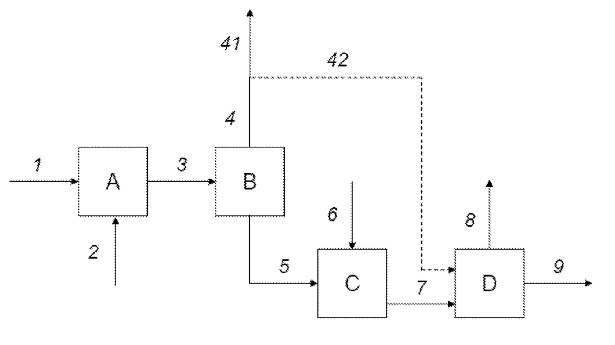
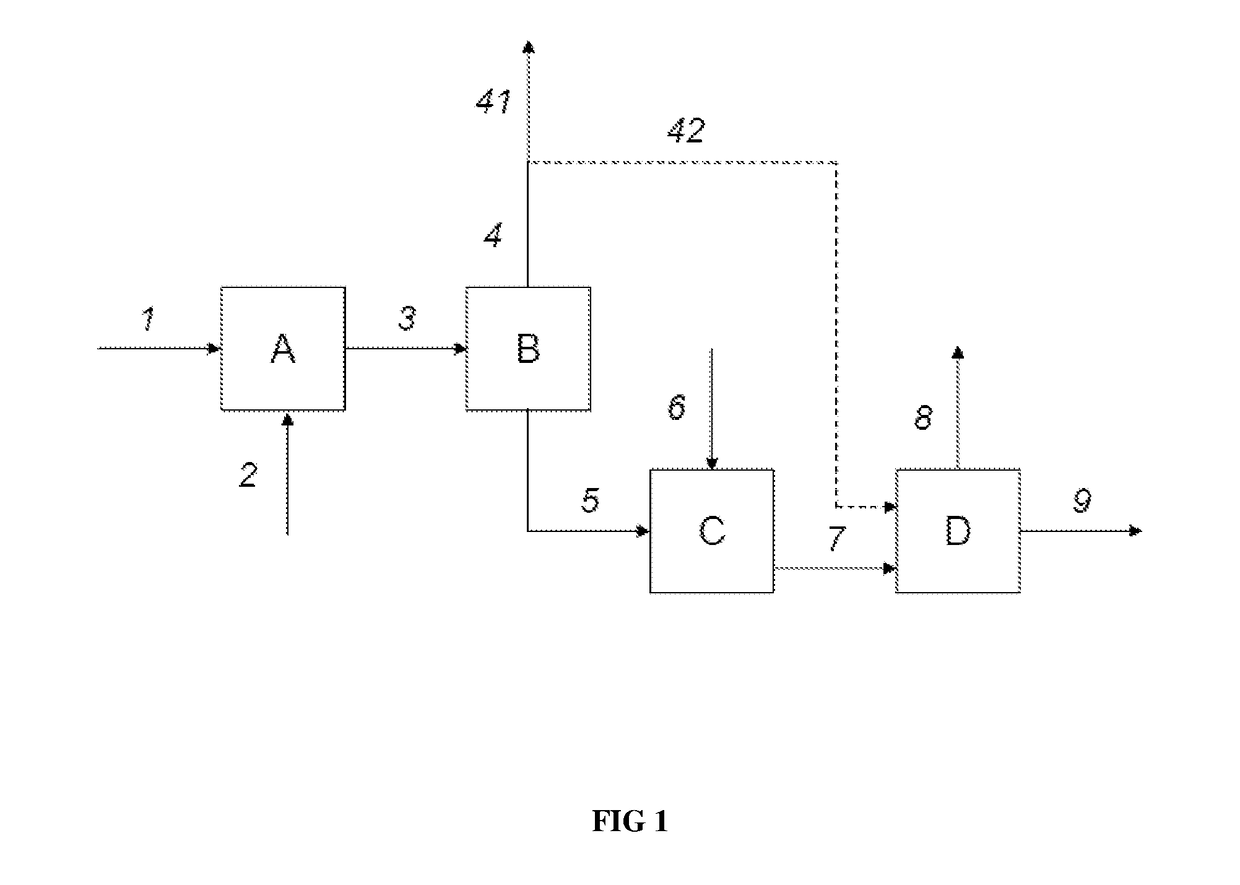
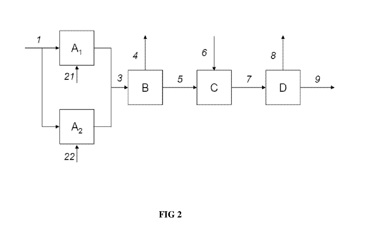
[0074]Process layout in accordance with the invention with low hourly space velocity (overall HSV=0.089 h−1) and low temperature

[0075]In this example, the present invention is illustrated in a process layout with two ebullated bed reactors disposed in series, operated at a low hourly space velocity (HSV) and at a low temperature and with a separation section.

Hydroconversion Section a)

[0076]The fresh feed of Table 1 was sent in its entirety to a section A for hydroconversion in the presence of hydrogen, said section comprising a three-phase reactor containing a NiMo / alumina hydroconversion catalyst with a NiO content of 4% by weight and a MoO3 content of 9% by weight, the percentages being expressed with respect to the total mass of catalyst. The section functioned in ebullated bed mode with an upflow of liquid and gas.

[0077]The conditions applied in the hydroconversion section A are shown in Table 6.

TABLE 6Operating conditionsSectionAP, totalMPa16Tem...


PUM

PropertyMeasurementUnit
temperatureaaaaaaaaaa
pressureaaaaaaaaaa
temperatureaaaaaaaaaa

Abstract

The invention concerns a process for the conversion of a heavy hydrocarbon feed, said process comprising the following steps: a) a step for hydroconversion of the heavy hydrocarbon feed in the presence of hydrogen in at least one or more three-phase reactors disposed in series or in parallel, containing at least one hydroconversion catalyst, so as to obtain a liquid effluent with a reduced Conradson carbon, metals, sulphur and nitrogen content, b) one or more optional steps for separating the effluent obtained from step a) in order to obtain at least one light liquid fraction boiling at a temperature of less than 350° C. and a heavy liquid fraction boiling at a temperature of more than 350° C., c) a step for hydroconversion of the liquid effluent obtained from the hydroconversion step a) in the case in which the separation step b) is not carried out, or of the heavy liquid fraction obtained from the separation step b) when said step b) is carried out, in the presence of hydrogen in at least one or more three-phase reactors disposed in series or in parallel and containing at least one hydroconversion catalyst, in which process the overall hourly space velocity employed is in the range 0.05 to 0.18 h−1.

Description

TECHNICAL FIELD OF THE INVENTION[0001]The present invention relates to a process for the conversion of a heavy hydrocarbon feed advantageously obtained either from a crude oil or from atmospheric and / or vacuum distillation of a crude oil and containing at least 80% by weight of a fraction with an initial boiling temperature of at least 300° C.PRIOR ART[0002]More precisely, the feeds which are treated in the context of the present invention are either crude oils or heavy hydrocarbon fractions obtained from the atmospheric distillation and / or vacuum distillation of a crude oil and containing at least 80% by weight of a fraction with an initial boiling temperature of at least 300° C., preferably at least 350° C. and more preferably at least 375° C., and preferably vacuum residues containing at least 80% by weight of a fraction with an initial boiling temperature of at least 450° C. and preferably at least 500° C. These feeds are generally hydrocarbon fractions with a sulphur content of...

Claims


Application Information

Patent Timeline
Patent Type & Authority Applications(United States)
IPC IPC(8): C10G65/12C10G47/04C10G47/12B01J23/28B01J23/755B01J21/04
CPCC10G65/12C10G47/04C10G47/12B01J23/28B01J23/755B01J21/04C10G2300/107C10G2300/1074C10G2300/1077C10G2300/4018C10G65/00
Inventor DREILLARD, MATTHIEUFEUGNET, FREDERICMARQUES, JOAOMOREL, FREDERIC
Owner INST FR DU PETROLE
Why Eureka
Try Eureka