Circuit board and battery connection module

a battery connection module and printed circuit board technology, applied in the field of printed circuit boards, to achieve the effect of saving the cost of circuit board replacement, reducing the area occupied by the fuse unit, and simple operation procedure at the time of repair

Inactive Publication Date: 2018-07-12
MOLEX INC
View PDF1 Cites 13 Cited by
  • Summary
  • Abstract
  • Description
  • Claims
  • Application Information

AI Technical Summary

Benefits of technology

[0005]Therefore, one object of the present disclosure is to provide a circuit board, which has a fuse unit with a simple circuit and in which the operation procedure at the time of the repair is more simple and convenient.
[0030]The present disclosure at least has the following effect: the area occupied by the fuse unit can be reduced by the simple circuit of the whole fuse unit, and the fuse unit can be repaired when the main fuse is fused so as to save the cost of replacing the circuit board, and the operation procedure at the time of the repair is more simple and convenient. Further, the plurality of spare fuses can be increased according to requirement, the number of repairs can be increased, so as to extend the service life of the circuit board. The connection strength between the busbar and the circuit board can be increased by the auxiliary connecting tab, so as to maintain the stability of electrical connections.

Problems solved by technology

Due to the fusing assemblies of the aforementioned fusing module are connected in series, and each fusing assembly comprises the connector and the fusing wire which are connected in parallel, it is not only need to occupy more area on the circuit board, but also the connector of the fusing assembly as spare needs to be soldered to form a current conductive path first, and then the soldering tin thereon needs to be removed to form the electrical disconnection when the fusing assembly as spare is to work, which is inconvenient.

Method used


Image

  • Circuit board and battery connection module
  • Circuit board and battery connection module
  • Circuit board and battery connection module

Examples


Embodiment Construction

[0042]Before the present disclosure is described in detail, it should be noted that like elements are indicated by the same reference numerals in the following description.

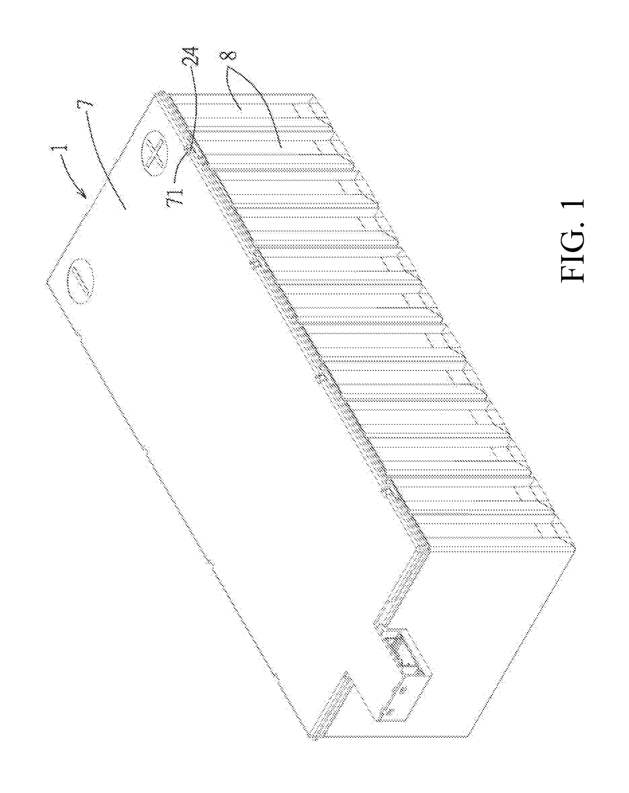
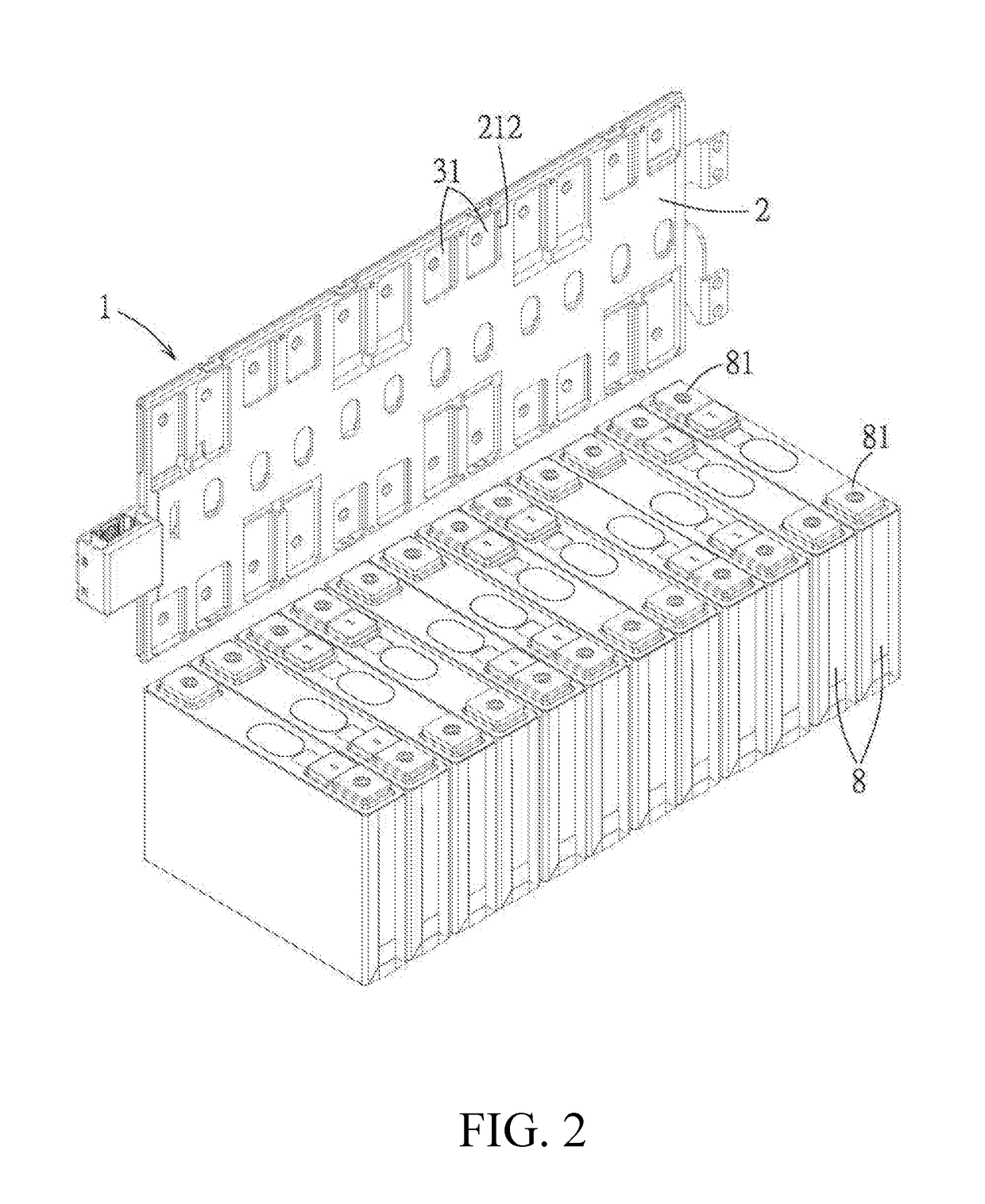
[0043]Referring to FIG. 1 and FIG. 2, an embodiment of a battery connection module 1 in the present disclosure is used to connect a plurality of batteries 8 arranged side by side.

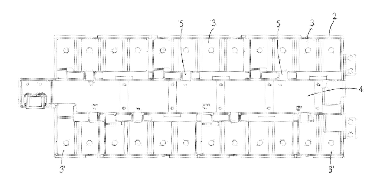
[0044]Referring to FIG. 2 to FIG. 5, the battery connection module 1 comprises an insulating frame 2, a plurality of busbars 3, a circuit board 4, a plurality of conductive connecting tabs 5, a plurality of auxiliary connecting tabs 5′, an extension connecting tab 6 and a cover 7.

[0045]The insulating frame 2 is used to be provided on the plurality of batteries 8 and has a body 21, the body 21 is formed with a plurality of accommodating grooves 211 correspondingly accommodating the plurality of busbars 3 and limiting the plurality of busbars 3 in position, and a plurality of hollow portions 212 are formed in each accommodating groove 211. ...


PUM

PropertyMeasurementUnit
current conductiveaaaaaaaaaa
areaaaaaaaaaaa
flexibleaaaaaaaaaa

Abstract

A circuit board and a battery connection module are provided. The circuit board has an insulating substrate and a plurality of circuit traces provided thereto. At least one of the traces is provided with a fuse unit. The fuse unit has a main fuse and at least one spare fuse. The main fuse has two main trace connection end portions respectively positioned at two ends of the main fuse and connected to the trace and a main fuse section connected between the two main trace connection end portions. The spare fuse has two trace connection end portions respectively positioned at two ends of the spare fuse and a fuse section connected between the two trace connection end portions, the fuse section and the main fuse section are spaced apart from each other and arranged side by side, and at least one of the two trace connection end portions is not connected with the trace so as to form an electrical disconnection with the trace, and after the main fuse section forms an electrical disconnection, the two trace connection end portions are connected to the trace so that a current conductive path is formed by the spare fuse and the trace.

Description

RELATED APPLICATIONS[0001]This application claims priority to Chinese Application No. 201710014976.8, filed Jan. 9, 2017, which is incorporated herein by reference in its entirety.TECHNICAL FIELD[0002]The present disclosure relates to a circuit board, and particularly relates to a printed circuit board and a battery connection module.BACKGROUND ART[0003]A fuse is often used for safety protection in a general circuit. For example, Chinese Patent issued publication No. CN203691758U discloses a flexible printed circuit board in which a fusing module is provided in a circuit thereof, the fusing module comprises two or more fusing assemblies which are connected in series, and each of the fusing assemblies comprises a connector and a fusing wire which are connected in parallel, the connector comprises two pads spaced apart from each other. The operating principle of the fusing module is: in order to make one of the fusing assemblies work, the two pads of the connector of the fusing assemb...

Claims


Application Information

Patent Timeline
Patent Type & Authority Applications(United States)
IPC IPC(8): H01M2/34H05K1/02H01M2/20H01M50/507H01M50/51H01M50/531H01M50/581
CPCH01M2/348H05K1/0293H05K1/028H01M2/202H05K2201/10181H05K2201/10037H02H7/18H01M2200/103H05K1/181H05K1/0213H01H85/046H01H85/12H01H85/143H01M50/51H01M50/507H01M50/531H05K1/118H02H3/046H02H3/08Y02E60/10H01M50/581
Inventor ZENG, SHANG XIU
Owner MOLEX INC
Why Eureka
Try Eureka