System and method for a multi system trust chain

a multi-system trust chain and trust chain technology, applied in the field of cyber security and the internet of things, can solve problems such as traffic encryption performed by the client application at the client system, throughput and scalability bottlenecks, and achieve the effect of facilitating an association and protecting confidentiality and integrity of data exchang

Active Publication Date: 2018-07-12
DIGICERT
View PDF4 Cites 16 Cited by
  • Summary
  • Abstract
  • Description
  • Claims
  • Application Information

AI Technical Summary

Benefits of technology

[0008]Connection oriented and connectionless (datagram) services leverage the Transport Layer Security (TLS) protocol for secure transport. The two-way handshake sequence between a local client application and a remote service may be extended to support a transitive trust chain. This requires a method to facilitate an association between the trusted peers and an intermediate trusted system in the network flow path, wherein the data is transported between peers without breaking end-to-end encryption during transit, thereby protecting confidentiality and integrity of the data exchange.

Problems solved by technology

However, OT endpoints inevitably traverse midstream security controls, such as network firewalls, to connect to IT applications and services for integration with analytics, processes and / or data repositories.
However, this bump in the wire approach introduces throughput and scalability bottlenecks because of session level decryption and encryption.
Further, traffic encryption performed by the client application at the client system poses challenges to content inspection engines for application identification and protocol or behavior based anomaly detection at intermediate (midstream, bump in the wire, man-in-the-middle (MITM)) network security devices.
However, such a method requires sharing of secrets by the server with the client and the intermediate appliance.
However, such signing does not constitute an end to end trust chain between systems and merely allows the intermediate CA to sign certificates on behalf of the root CA.

Method used


Image

  • System and method for a multi system trust chain
  • System and method for a multi system trust chain
  • System and method for a multi system trust chain

Examples


Embodiment Construction

[0020]Although the disclosure is illustrated and described herein with reference to specific embodiments, the invention is not intended to be limited to the details shown herein. Rather, various modifications may be made in the details within the scope and range of equivalents of the claims and without departing from the scope of the disclosure.

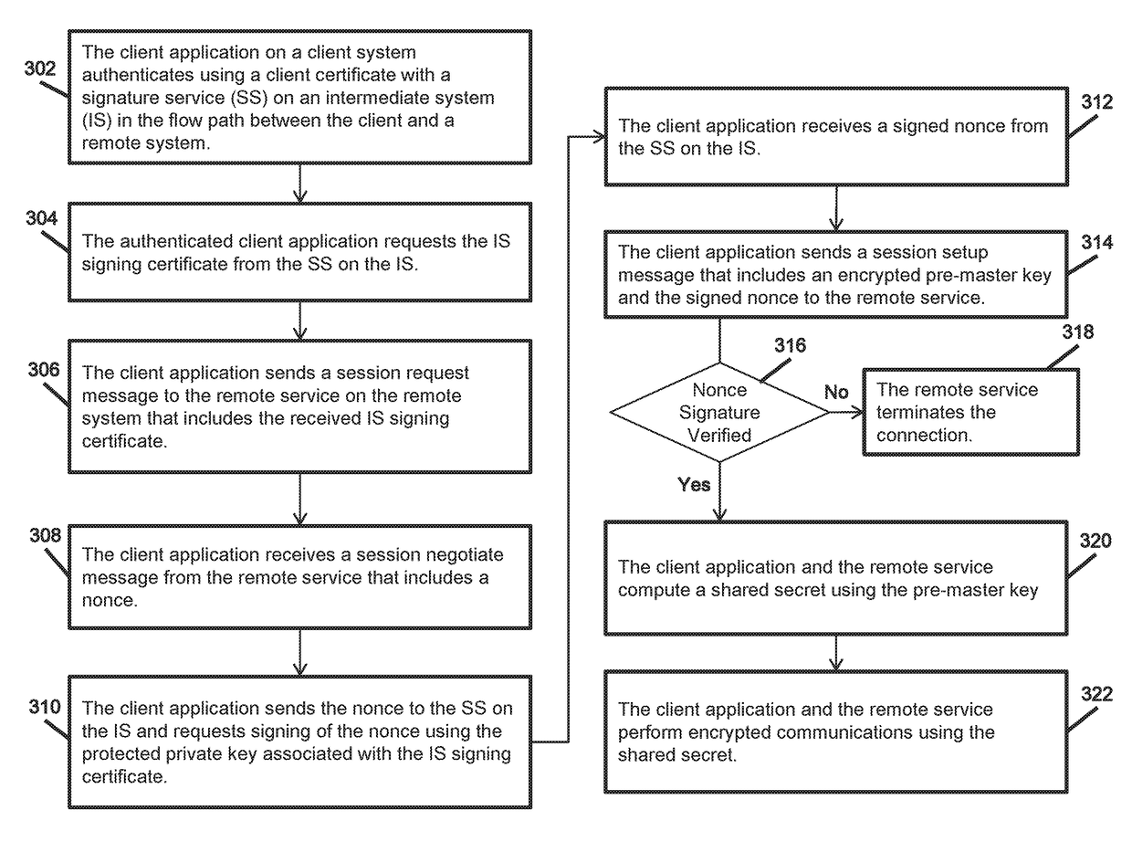
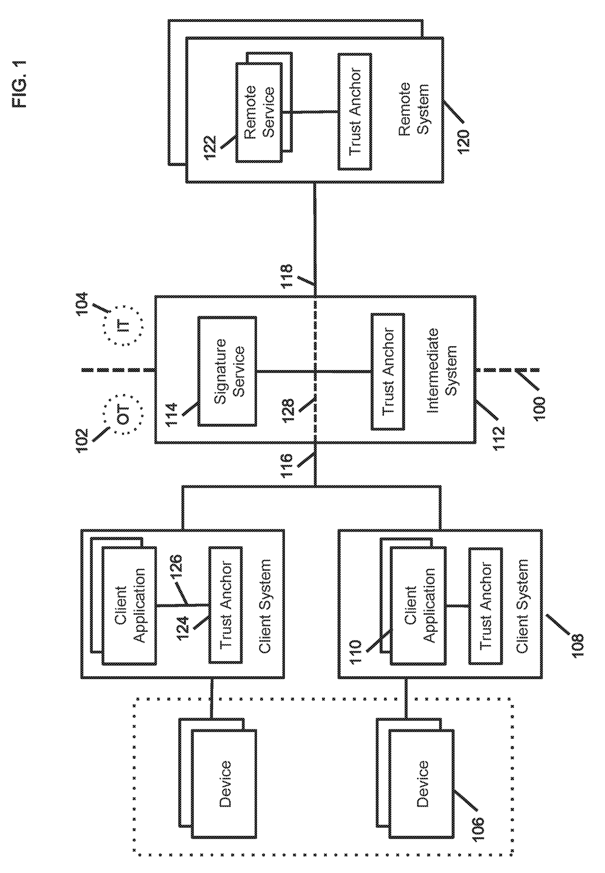
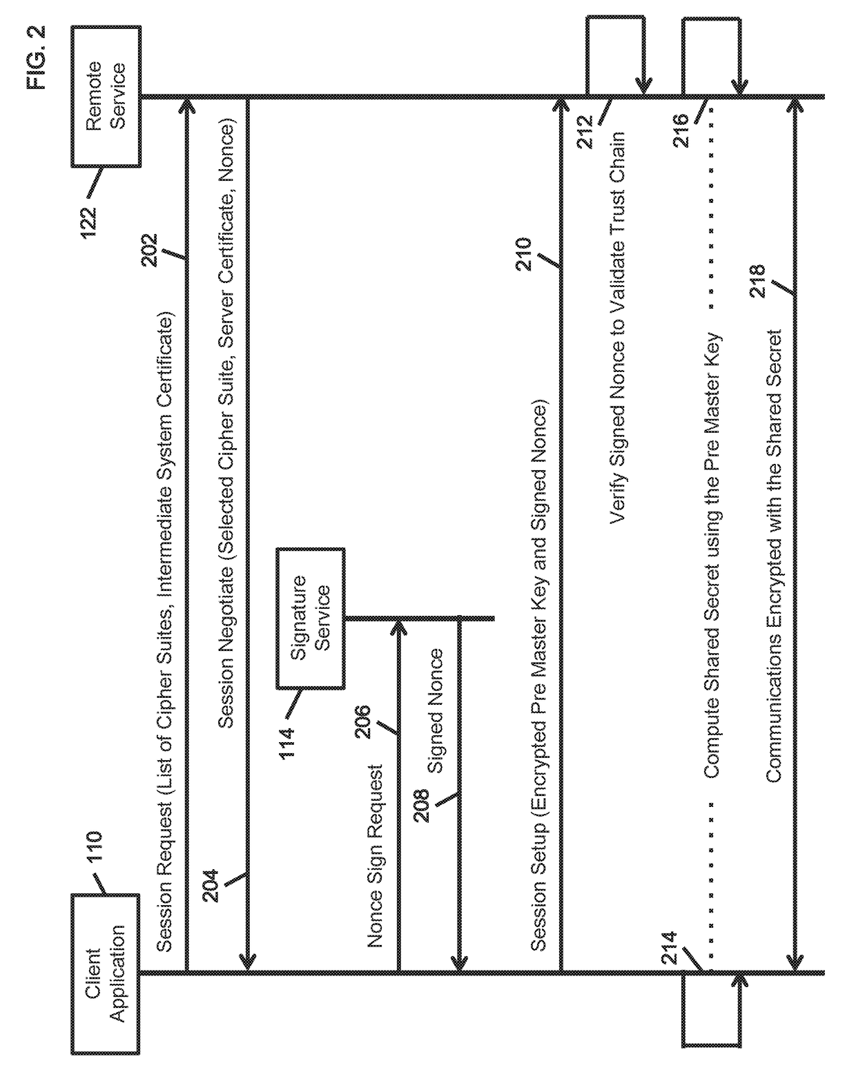
[0021]Application identification in the industrial IoT requires both a certificate chain and trust anchors (i.e. secure elements) to protect private keying materials issued to the application on the host system. Establishing (and extending) the trust across the network requires an end to end trust chain that can traverse trusted intermediate network elements without requiring computationally intensive and cryptographically intrusive deep content inspection for protocol and behavior based anonaly detection. An innovative method to establish an end to end multi system trust chain that overcomes such scalability and privacy limitations in cross-...


PUM


Abstract

The method provides a multi system trust chain between a client system and a remote system in a secure connection, wherein an intermediary system associated with the network flow path serves as a signing entity to establish an end to end transitive trust. The intermediate system is a corroborative entity in the operations technology (OT) realm of the client system. The remote system serves as the host for a plurality of services in the information technology (IT) realm. A two way handshake during the initial secure exchange protocol between a local client application and a remote service is extended to a three way handshake that includes a nonce issued by the remote service on the remote system and a digital signature for the nonce issued by a signature service on an associated intermediate system. The nonce signature is verified authoritatively at the remote system based on the signing certificate of the intermediate system for explicit proof of association.

Description

CROSS-REFERENCE TO RELATED APPLICATIONS[0001]This application claims the benefit under 35 U.S.C. § 119(e) of U.S. Provisional Patent Application No. 62 / 444,686, entitled “SYSTEM AND METHOD FOR A MULTI SYSTEM TRUST CHAIN”, filed on Jan. 10, 2017, which is incorporated herein by reference in its entirety for all purposes.BACKGROUND OF THE DISCLOSUREField of the Disclosure[0002]This invention relates to the field of cyber security and the Internet of Things (IoT), more particularly, to a system and method to establish an end to end multi system trust chain between a client system and a remote system in a secure connection, wherein an intermediary system in the network flow path serves as a signing entity to establish transitive trust.Description of the Related Art[0003]An end-to-end trust chain may be established between endpoints (devices and gateways) deployed in the operational technology (OT) realm and remote services hosted in the information technology (IT) realm. This requires a...

Claims


Application Information

Patent Timeline
Patent Type & Authority Applications(United States)
IPC IPC(8): H04L29/06H04L9/32H04L9/30
CPCH04L63/0428H04L9/30H04L9/3263H04L9/3247H04L63/0281H04L63/0823H04L63/126H04L9/0838H04L9/3268H04L9/50
Inventor KUMAR, SRINIVASRAMAN, GOPALGUPTA, ATULPANDHARE, SHASHANK JAYWANT
Owner DIGICERT
Why Eureka
Try Eureka