Automatic welding machine

a welding machine and automatic technology, applied in the direction of welding apparatus, electrode supporting devices, manufacturing tools, etc., can solve the problem and achieve the effect of reducing the accuracy of positioning the tip of the welding torch

Inactive Publication Date: 2018-07-19
NTN CORP
View PDF2 Cites 0 Cited by
  • Summary
  • Abstract
  • Description
  • Claims
  • Application Information

AI Technical Summary

Benefits of technology

[0009]However, in the above automatic welding machines using the link actuator, peripheral devices such as a cooling water device and a wire supply device are connected to a welding torch via cables, and thus tension may be applied to the welding torch due to welding motion, so that the accuracy of positioning the tip of the welding torch may be decreased.
[0010]An object of the present invention is to provide an automatic welding machine that has a compact configuration but can make fine motion at high speed with high accuracy and prevents the accuracy of positioning the tip of a welding torch from being decreased due to welding motion.

Problems solved by technology

However, in the above automatic welding machines using the link actuator, peripheral devices such as a cooling water device and a wire supply device are connected to a welding torch via cables, and thus tension may be applied to the welding torch due to welding motion, so that the accuracy of positioning the tip of the welding torch may be decreased.

Method used


Image

  • Automatic welding machine
  • Automatic welding machine
  • Automatic welding machine

Examples


Embodiment Construction

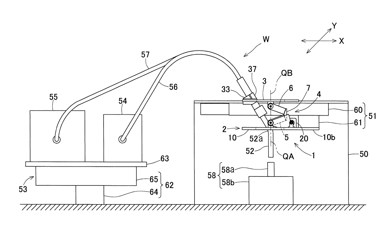
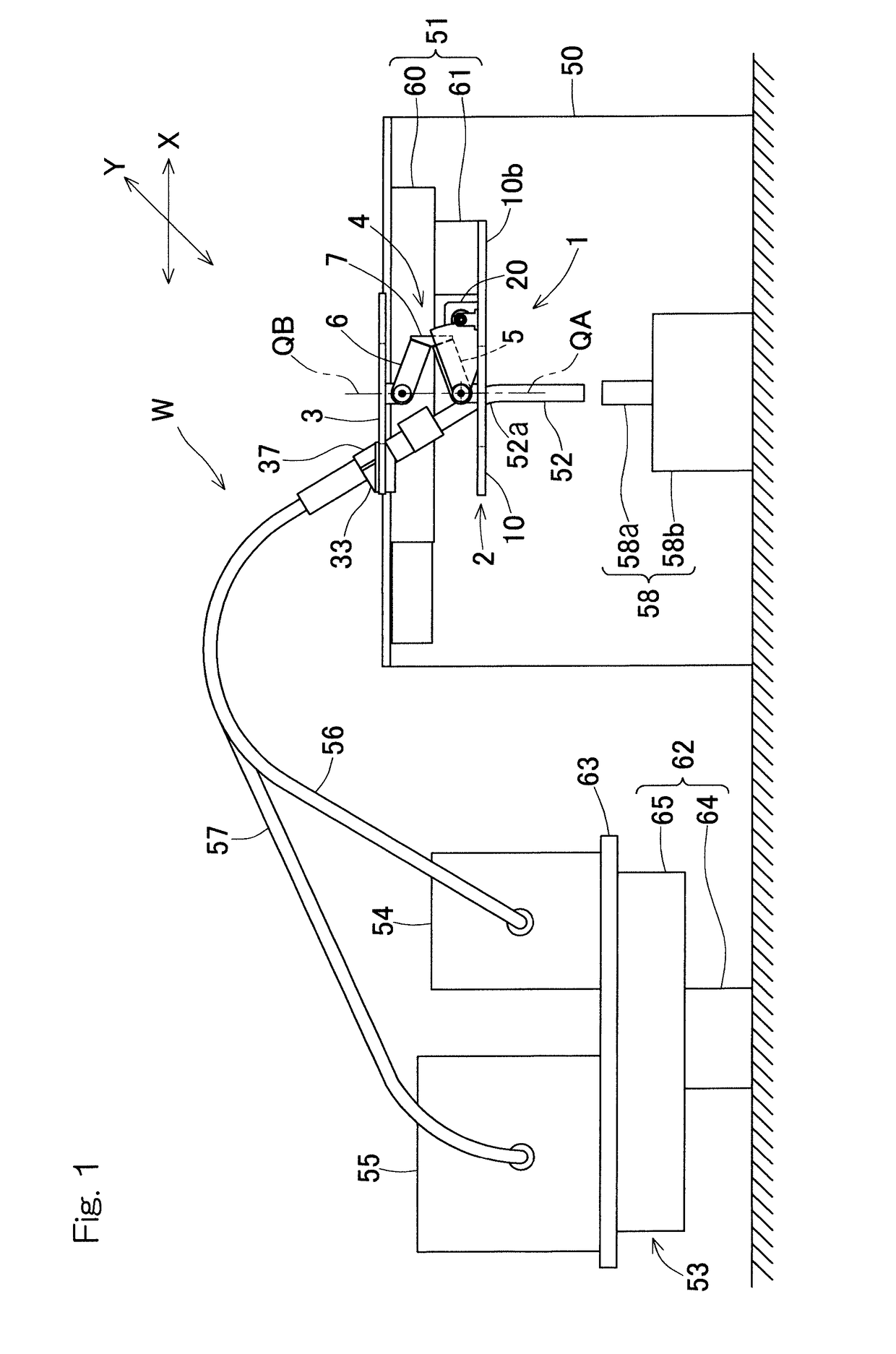
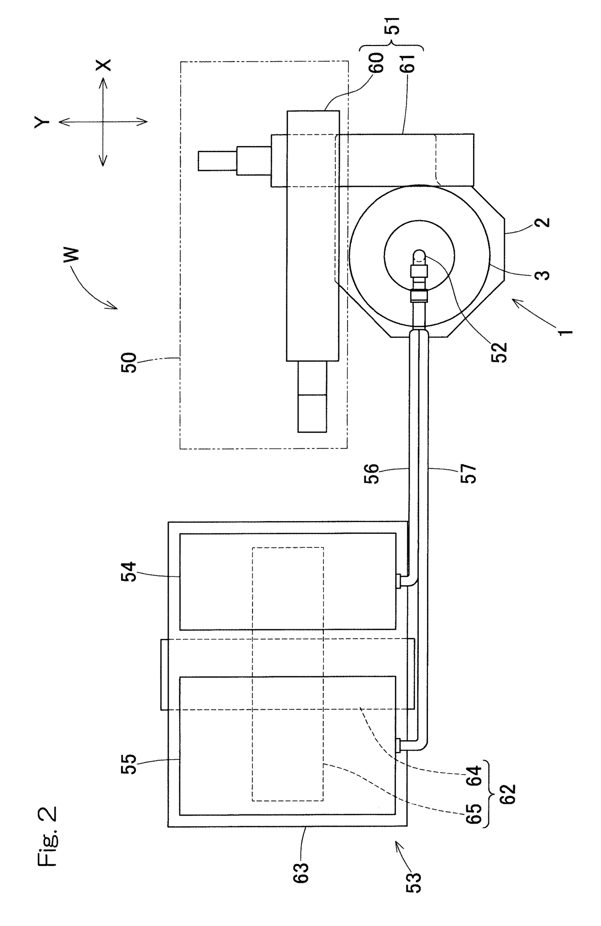
[0034]An embodiment of the present invention will be described with reference to FIG. 1 to FIG. 7.

[0035]As shown in FIG. 1 and FIG. 2, an automatic welding machine W is an automatic welding machine with MIG (Metal Inert Gas) welding, wherein: a link actuator 1 is mounted on a mount 50 fixed to the ground (or a workbench), via a linear motion mechanism 51; and a welding torch 52 is mounted on the link actuator 1. In addition, a movement mechanism 53 is mounted on the ground and at a location away from the mount 50, and a wire supply device 54 and a cooling water device 55, which are peripheral devices, are mounted on the movement mechanism 53. The wire supply device 54 and the cooling water device 55 are connected to the welding torch 52 via cables 56 and 57, respectively.

[0036]The linear motion mechanism 51 includes an XY stage including two linear motion actuators which are combined with each other and have respective axes, that is, an X-axis and a Y-axis. Specifically, the linear ...


PUM

PropertyMeasurementUnit
bend angleaaaaaaaaaa
degrees of freedomaaaaaaaaaa

Abstract

An automatic welding machine includes a link actuator in which a distal end side link hub is coupled to a proximal end side link hub via three or more link mechanisms and the position of the distal end side link hub relative to the proximal end side link hub can be arbitrarily changed. The automatic welding machine is provided with one or more linear motion actuators configured to cause the proximal end side link hub of the link actuator to advance / retract relative to a mount along respective axes, and a welding torch is mounted on the distal end side link hub. The automatic welding machine further includes a movement mechanism on which peripheral devices connected to the welding torch via cables are mounted so as to be movable in one or more axial directions.

Description

CROSS REFERENCE TO THE RELATED APPLICATION[0001]This application is based on and claims Convention priority to Japanese patent application No. 2015-167601, filed Aug. 27, 2015, the entire disclosure of which is herein incorporated by reference as a part of this application.BACKGROUND OF THE INVENTIONField of the Invention[0002]The present invention relates to an automatic welding machine that is used in a manufacturing process or the like and that can perform automatic fine welding work at high speed with high accuracy, without manpower.Description of Related Art[0003]Conventional automatic welding machines are generally equipped with a welding torch at a distal end of an articulated robot as proposed in Patent Documents 1 to 3. These automatic welding machines using the articulated robot have an advantage in having a wide work range. On the other hand, in the automatic welding machines using the articulated robot, the size of a robot body is large, and thus, in consideration of the...

Claims


Application Information

Patent Timeline
Patent Type & Authority Applications(United States)
IPC IPC(8): B23K9/127B23K9/28B23K9/173
CPCB23K9/173B23K9/127B23K9/28B23K9/12B23K9/287
Inventor KONAGAI, NAOYAISOBE, HIROSHISAKATA, SEIGOYAMADA, HIROYUKI
Owner NTN CORP
Why Eureka
Try Eureka