Air conditioning device for vehicle

a technology for air conditioning devices and vehicles, which is applied in the direction of compression machines, lighting and heating apparatus, and heating types, etc. it can solve the problems of degrading the coefficient of performance of a heat pump cycle, increasing the opening degree of the expansion valve to delay, and reducing the heat absorbed by the heat absorber. , the effect of reducing the amount of heat absorbed by the heat absorber

Active Publication Date: 2018-07-19
DENSO CORP
View PDF12 Cites 11 Cited by
  • Summary
  • Abstract
  • Description
  • Claims
  • Application Information

AI Technical Summary

Benefits of technology

[0010]With this configuration, as shown in an example in FIG. 6, when the controller performs the frost delay control, a refrigerant pressure on a high-pressure side increases and therefore a difference in enthalpy between the refrigerant at an outlet and the refrigerant at an inlet of the heat absorber reduces. As a result, an amount of heat absorbed by the heat absorber reduces, which delays the frost formation on the heat absorber.

Problems solved by technology

In the above-described conventional art, however, the opening degree of the expansion valve is increased to delay the frost formation on the exterior heat exchanger when the frost formation is likely to occur on the exterior heat exchanger.
As a result, the subcooling degree of refrigerant flowing out of a condenser deviates from the target subcooling degree, which degrades a coefficient of performance COP of a heat pump cycle.

Method used


Image

  • Air conditioning device for vehicle
  • Air conditioning device for vehicle
  • Air conditioning device for vehicle

Examples


first embodiment

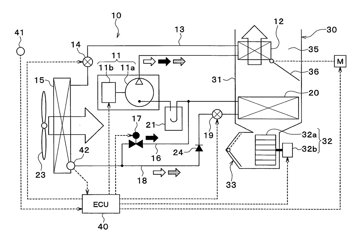
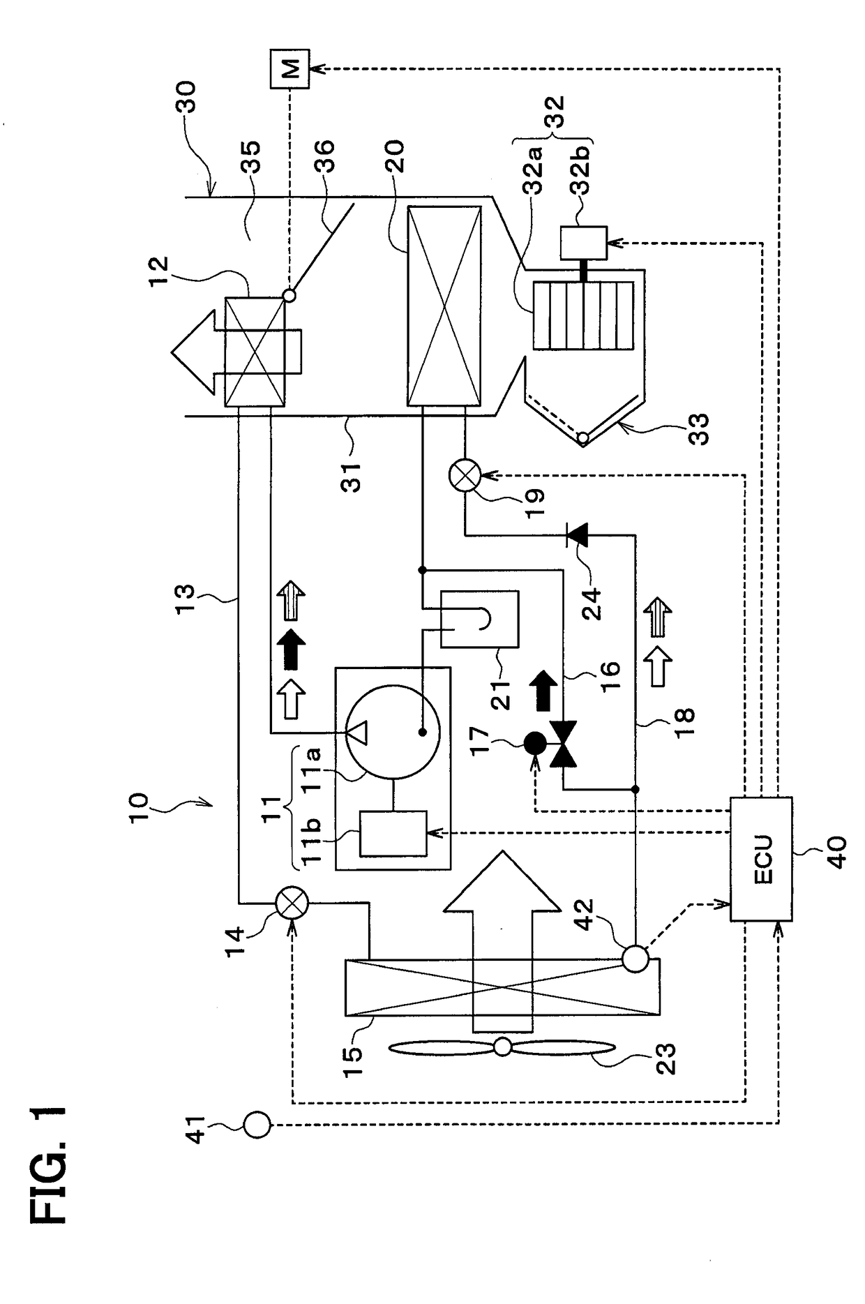
[0027]An air conditioning device 1 for a vehicle shown in FIG. 1 is an air conditioning device that air conditions an inside of a vehicle compartment. The air conditioning device 1 for the vehicle is mounted to a hybrid vehicle. The hybrid vehicle is a vehicle that obtains drive force for traveling of the vehicle from an engine and an electric motor for traveling.

[0028]The air conditioning device 1 for the vehicle has a refrigeration cycle device 10. The refrigeration cycle device 10 cools or heats air to be blown into the vehicle compartment.

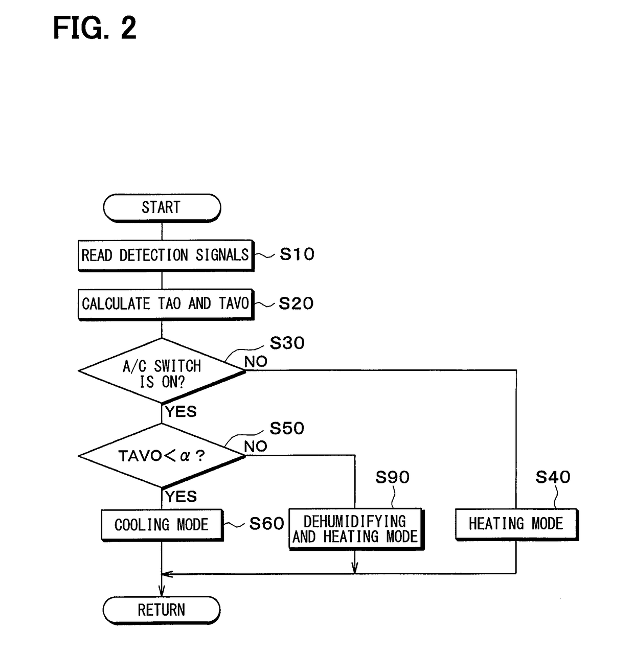
[0029]The refrigeration cycle device 10 can switch between a refrigerant flow path for a cooling mode, a refrigeration flow path for a dehumidification heating mode, and a refrigeration flow path for a heating mode.

[0030]In the cooling mode, a cooling operation for cooling the inside of the vehicle compartment is performed. In the dehumidification heating mode, a dehumidification heating operation for heating while dehumidifying the inside of t...

second embodiment

[0156]In the first embodiment, the high-pressure refrigerant discharged from the compressor 11 dissipates heat into the air in the interior condenser 12. In the present embodiment, as shown in FIG. 10, high-pressure refrigerant discharged from a compressor 11 dissipates heat into heat medium in a refrigerant-heat medium heat exchanger 25 and the heat medium to which the heat is dissipated in the refrigerant-heat medium heat exchanger 25 dissipates heat into air in a heater core 34. For example, the heat medium is ethylene glycol antifreeze which is what is called LLC.

[0157]The refrigerant-heat medium heat exchanger 25 and the heater core 34 are radiators that dissipate heat of the refrigerant discharged from the compressor 11, thereby heating the air by utilizing the heat dissipated from the refrigerant. The heater core 34 is a heat medium-air heat exchanger that performs heat exchange between the heat medium and the air.

[0158]The heater core 34 is housed in a case 31 of the interio...

third embodiment

[0164]In the second embodiment, the air mix door 36 reduces the volume of the air passing through the heater core 34 to thereby delay the frost formation on the exterior heat exchanger 15 in the frost formation delaying mode. In the present embodiment, as show in in FIGS. 11 and 12, a volume of heat medium discharged from the pump 51 is reduced to thereby delay frost formation on the exterior heat exchanger 15 in a frost formation delaying mode.

[0165]In the frost formation delaying mode, the controller 40 sets a control signal output to the pump 51 so that a volume V2 of the heat medium discharged from the pump 51 becomes smaller than a volume V1 of the heat medium discharged from the pump 51 in a normal heating mode. The volume V2 of the heat medium discharged by the pump 51 in the frost formation delaying mode is smaller than the volume V1 of the heat medium discharged by the pump in the normal heating mode.

[0166]In this way, the volume of the heat medium flowing through the refri...


PUM


Abstract

An air conditioning device has a blower, a compressor, a radiator, a decompressor, a heat absorber, and a controller. The compressor compresses and discharges a refrigerant. The radiator dissipates a heat of the refrigerant to the air thereby heating the air. The decompressor decompresses the refrigerant after the heat of the refrigerant is dissipated in the radiator. The refrigerant decompressed in the decompressor absorbs heat from outside air in the heat absorber. The controller determines whether the heat absorber is in a frosted state in which a frost is formed on the heat absorber or whether the heat absorber is in an estimated frosted state in which a frost is possibly formed on the heat absorber. The controller performs a frost delay control to delay a formation of the frost when the controller determines that the heat absorber is in the frosted state or the estimated frosted state.

Description

CROSS REFERENCE TO RELATED APPLICATION[0001]This application is based on and claims the benefit of priority from Japanese Patent Application No. 2015-156200 filed on Aug. 6, 2015. The entire disclosure of the application is incorporated herein by reference.TECHNICAL FIELD[0002]The present disclosure relates to an air conditioning device for a vehicle.BACKGROUND ART[0003]Conventionally, an air conditioning device for a vehicle heats an inside of a vehicle compartment by using a heat pump cycle. In such an air conditioning device for a vehicle, condensed water on an exterior heat exchanger freezes to form frost when a temperature of refrigerant flowing through the exterior heat exchanger falls below a dew-point temperature. If the frost is formed on the exterior heat exchanger, an amount of heat absorbed from outside air in the exterior heat exchanger reduces, which significantly degrades heating performance.[0004]Patent Literature 1 discloses an air conditioning device for a vehicle ...

Claims


Application Information

Patent Timeline
Patent Type & Authority Applications(United States)
IPC IPC(8): B60H1/00F24F11/89F25B47/02F25B6/04
CPCB60H1/00028F24F11/89F25B47/02F25B6/04B60H1/00385B60H1/00785F25B9/002F25B2400/0411B60H2001/3266B60H1/00921F24F11/42F24F11/86F25B5/04F25B49/025F25B2400/0409F25B2600/0253F25B2700/2106B60H2001/00961F25B41/22
Inventor NOMURA, TOMOYUKIKUWAHARA, MIKIHARU
Owner DENSO CORP
Why Eureka
Try Eureka