
Grinder pump and cutting assembly thereof

a technology of grinding pump and cutting assembly, which is applied in the direction of machines/engines, grain treatment, liquid fuel engines, etc., can solve the problems and reducing the wear rate of the cutting assembly, etc. , to achieve the effect of reducing the life of the grinding pump and high wear ra

Active Publication Date: 2018-07-19
LIBERTY PUMPS
View PDF1 Cites 10 Cited by
  • Summary
  • Abstract
  • Description
  • Claims
  • Application Information

AI Technical Summary

Benefits of technology

The present invention solves the problem of high wear and reduced life of a cutting assembly in a grinder pump by providing a cutting plate with multiple cutting edges that are distributed over a range of radial locations. This design allows for a shearing action with the cutter plate, distributing the wear on the cutting blades evenly and extending the life of the cutting assembly. The cutting ports may be located at a unique polar coordinate on the outer cutter surface for each cutting blade, further distributing the wear.

Problems solved by technology

Such solids have a wide variety of properties that are adverse to the operation of the pump, including high shear strength, abrasiveness, hardness, elasticity, and / or plasticity.
Materials that are abrasive may gradually wear away the cutting edges of the grinding parts of the pump.
Materials that have high shear strength and / or high hardness may shatter or deform the cutting edges of the grinding parts of the pump.
This high degree of localization of shearing action results in a relatively high rate of wear of the cutter plate and / or cutter blade at the shearing locations, thus reducing the life of the grinder pump: at some point, when the wear or impact damage to the shearing regions of the cutting assembly become excessive, and the pump is no longer able to grind the solid materials commonly present in the particular application, it must be replaced.
Thus another problem in grinder pump operation occurs, because instead of being cleanly cut up into smaller parts, these materials may deform and “gum up” or associate into fibrous string-like materials, and clog the grinder pump.
Fibrous, string-like materials, whether formed by association of ground solids during the grinding process, or present as fibrous incoming solids, are particularly difficult to shred with a grinder pump.
Once the shaft and central region of a pump impeller are shrouded with wrapped fibrous material, it is difficult to dislodge such materials.
There is no effective way to scrape the shrouded regions clean, and the liquid flow patterns within the pump volute act to retain the fibrous material in place.
Additionally, because this internal region of a grinder pump is hidden from view (and it is undesirable to perform any routine inspection of the pump, given the contents of the fluid stream), such a clogging problem goes undetected for a prolonged period of time.
In sewage grinding applications, typically little or no instrumentation (such as pressure and- / or flow) is provided, and the users (e.g., homeowners) are not knowledgeable about pumps.
Thus a grinder pump may be operated until a clogging problem progresses to the point of the pump being unable to perform its intended task before it is noticed.
At that point, the situation is urgent, and the tasks required to solve the problem are much more unpleasant.

Method used


Image

  • Grinder pump and cutting assembly thereof
  • Grinder pump and cutting assembly thereof
  • Grinder pump and cutting assembly thereof

Examples


Embodiment Construction

[0027]For a general understanding of the present invention, reference is made to the drawings. In the drawings, like reference numerals have been used throughout to designate identical elements. The drawings are to be considered exemplary, and are for purposes of illustration only. The dimensions, positions, order and relative sizes reflected in the drawings attached hereto may vary.

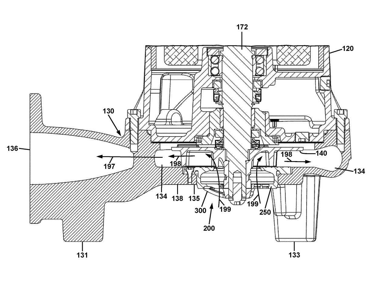
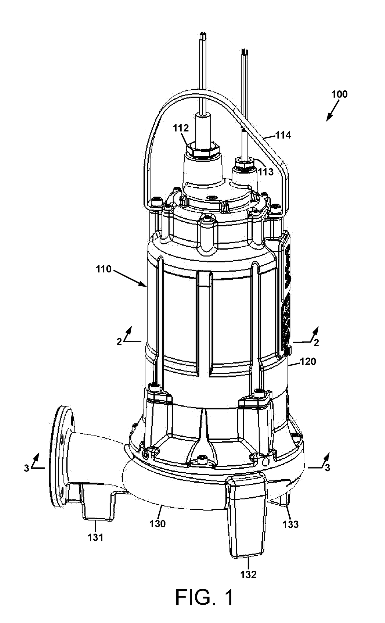
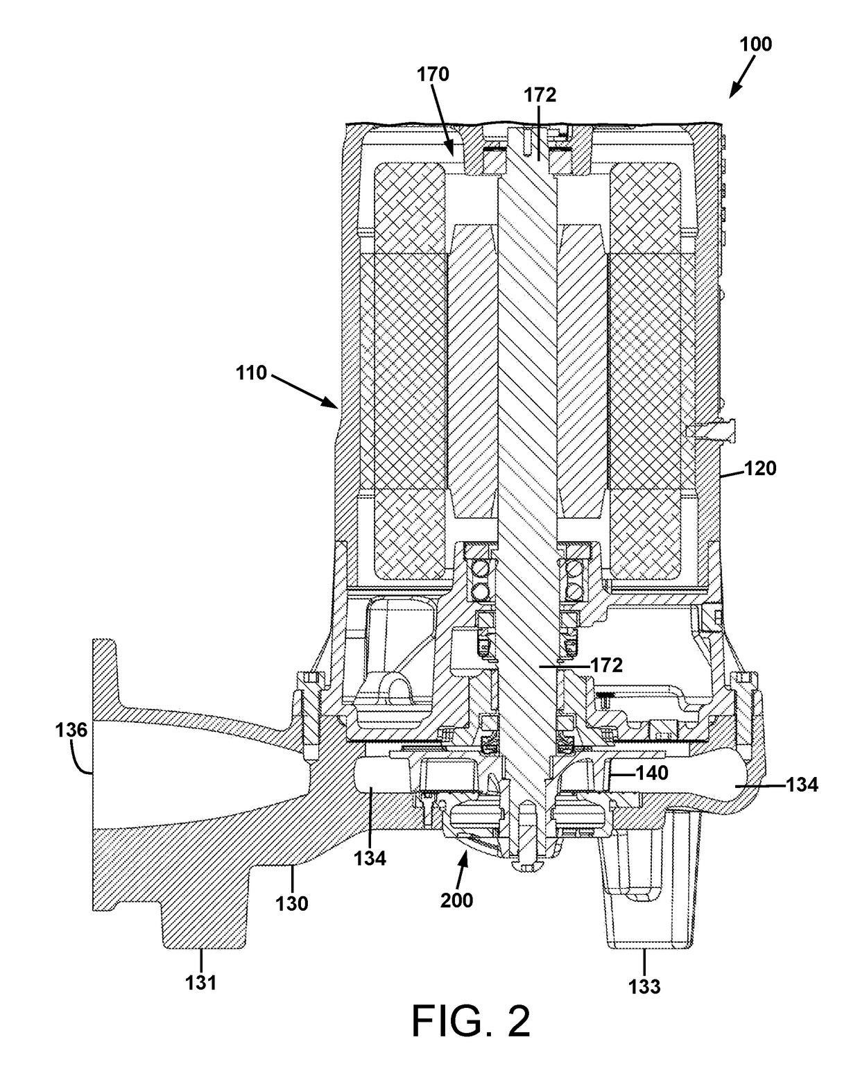
[0028]In the following disclosure, a cutting assembly is described in the context of its use in a grinder pump. However, it is not to be construed as being limited only to use in grinder pumps. The cutting assembly of the present disclosure is adaptable to any use in which reducing the size of suspended solids in a liquid stream is desirable to be provided. Additionally, this disclosure may identity certain components with the adjectives “top,”“upper,”“bottom,”“lower,”“left,”“right,” etc. These adjectives are provided in the context of use of the cutting assembly in a grinder pump, and in the context of ...


PUM


Abstract

A cutting assembly and a grinder pump including the cutting assembly are disclosed. The cutting assembly includes a cutting plate that has a plurality of cutting ports with cutting edges that are distributed over a range of radial locations of the plate. The cutting edges of the cutting ports define a series of cutting regions of the cutting blades of a rotary cutter that operate in a shearing action with the cutter plate. The cutting action by the blades of the rotary cutter is distributed over nearly the entire lengths of the cutting edges of the cutting blades, thereby distributing the wear on the cutting blades evenly, and extending cutting assembly life.

Description

BACKGROUNDTechnical Field[0001]Grinding impeller and cutting assemblies for grinder pumps, for reducing the size of suspended solids in a liquid stream and simultaneously pumping the liquid stream.Description of Related Art[0002]Grinder pumps are commonly used in liquid transfer applications that require the grinding of large solid or semisolid materials contained in a liquid, in order to grind, cut, or shred such materials. Ultimately, such solid or semisolid materials are reduced in size to the point where a slurry is formed, which is more easily pumped or otherwise transported, and which is more disposable than the solids themselves. Grinder pumps typically have an axial inlet connected to a pumping chamber, and a driven shaft extending through the pumping chamber and into the inlet. The shaft rotates a cutting cylinder in proximity to an annular ring, or a cutting disk in proximity to a cutter plate, thereby providing the cutting action of the pump. Numerous other variations and...

Claims


Application Information

Patent Timeline
Patent Type & Authority Applications(United States)
IPC IPC(8): F04D29/22B02C18/00F04D1/00F04D29/42F04D29/043
CPCF04D29/2288B02C18/0092B02C2201/063F04D29/426F04D29/043F04D1/00F04D7/045F04D13/086
Inventor POHLER, DONALD M.
Owner LIBERTY PUMPS
Learn More