
Cam ring for an injection pump

a technology of injection pump and cam ring, which is applied in the direction of positive displacement liquid engine, trunk piston, plunger, etc., can solve the problems of no longer ensuring an even application of force to the displacer element via this bearing surface, no longer a sufficiently even surface contact, and higher wear and material fatigue rate, so as to improve the performance of the pump and reduce the frictional heat , good solid lubricant

Inactive Publication Date: 2008-05-15
GLEITLAGER +1
View PDF5 Cites 5 Cited by
  • Summary
  • Abstract
  • Description
  • Claims
  • Application Information

AI Technical Summary

Benefits of technology

The present invention solves the problem of ensuring a tight fit between the low-friction bearing means and the cam ring, while also preventing fatigue and wear of the cam ring. This is achieved by applying a sliding-layer material directly to the surface of the cam ring, which reduces the need for a metal support or carrier layer. The sliding-layer material is made of a polymer-based sliding-layer material with friction-reducing filler material, and can be sprayed onto the surface or applied using an adhesion-favoring agent. The surface of the cam ring is roughened to improve adhesion, and phosphatization or other surface treatments can further enhance the adhesion. The use of a sliding-layer material with these components can allow for a more compact design with the same external dimensions and can also improve the performance of the cam ring in high-pressure injection pumps and diesel engines.

Problems solved by technology

When the foot or shoe section of a displacer element rests against this warped surface, there is no longer the guarantee of an even application of force to the displacer element via this bearing surface.
There is no longer a sufficiently even surface contact.
This is accompanied by a higher rate of wear and material fatigue.

Method used


Image

  • Cam ring for an injection pump
  • Cam ring for an injection pump

Examples


Embodiment Construction

[0032] The following description is merely exemplary in nature and is not intended to limit the present disclosure, application, or uses.

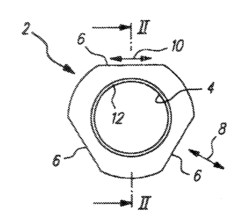
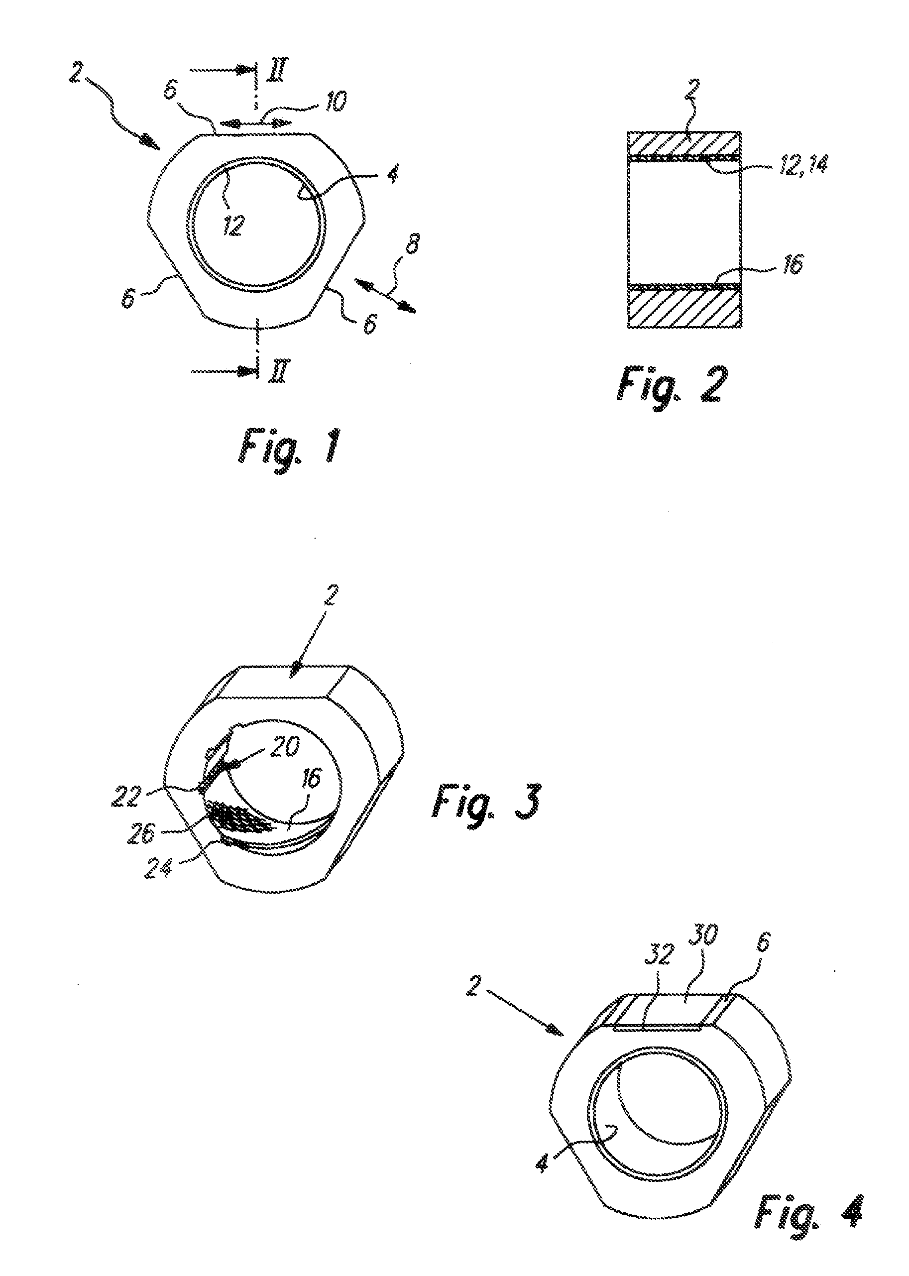
[0033]FIGS. 1 and 2 show two views of an inventive cam ring 2, particularly for use in a high-pressure injection pump of a diesel internal combustion engine. The cam ring 2 is compact and has a cylindrical shape in the widest sense. It features a central opening 4 for a shaft section driven in a slightly eccentric manner. On its outer circumference, the cam ring 2 features three flattened, level, outer sections 6, against each of which a displacer element (piston element) can rest. With the slightly eccentric drive of the aforementioned shaft section, each displacement element respectively is moved back and forth in the direction of the double arrow 8, whereby a foot section that rests against the outer section 6 of the respective displacement element executes a sliding movement, back and forth, in the planar direction of the flattened outer secti...


PUM


Abstract

The invention relates to a cam ring (2) for an injection pump for an internal combustion engine, comprising a round opening (4) for a shaft section, which can be eccentrically driven, and comprising a flattened outer section (6) against which a displacer element of the injection pump can be supported. A bush-shaped low-friction bearing means (12) for mounting the shaft section is provided inside the opening (4) of the cam ring (2). In order to reduce the problematic effects of pressing in the low-friction bearing means into the opening, the cam ring is designed so that the low-friction bearing means (12) in one form comprises a polymer-based bearing coating material (14) with friction-reducing fillers, which is directly placed upon the surface (16) of the cam ring (2) that delimits the opening (4).

Description

CROSS-REFERENCE TO RELATED APPLICATIONS [0001] This application is a continuation of International Application No. PCT / EP2006 / 006888 filed on Jul. 14, 2006, which claims the benefit of DE 10 2005 035 082.8, filed Jul. 21, 2005. The disclosures of the above applications are incorporated herein by reference.FIELD [0002] The invention relates to injection pumps for an internal combustion engines. BACKGROUND [0003] The statements in this section merely provide background information related to the present disclosure and may not constitute prior art. [0004] In the case of known cam rings, the low-friction bearing means is designed in the form of a plain bearing bushing that is made of steel / plastic composite. It comprises a support layer made of steel (steel back) and a porous carrier layer, which is usually made of bronze, into whose pores a polymer-based sliding-layer material is introduced. These kinds of plain bearing bushings are produced from an endless strip material, from which t...

Claims


Application Information

Patent Timeline
Patent Type & Authority Applications(United States)
IPC IPC(8): F16J1/10
CPCF04B1/0413
Inventor BICKLE, WOLFGANGBICKLE, RUEDIGERNIGRIN, UWE
Owner GLEITLAGER
Learn More