
Apparatus and method for measuring venous pressure

Active Publication Date: 2018-07-26
NIHON KOHDEN CORP
View PDF0 Cites 0 Cited by
  • Summary
  • Abstract
  • Description
  • Claims
  • Application Information

AI Technical Summary

Benefits of technology

The invention is about a device and technique for accurately measuring the pressure of a vein without inserting a needle. This makes it easier to monitor the flow of blood and diagnose potential health issues.

Problems solved by technology

With this method, however, because the venous pressure is measured at the time when the venous blood restarts to flow from the congested state, the venous pressure cannot be measured under a natural condition of a body of the subject.
Therefore, the venous pressure measurement apparatus of the second related art can obtain pulse waves that correspond only to such a change width (e.g., 5 mmHg) of the pressure, and hence the accuracy of the calculated venous pressure may not be sufficiently high.
Further, signal components of pulse wave detection signals are very small.
Thus, when noises are included in the pulse wave detection signals, the venous pressure calculated by the venous pressure measurement apparatus of the second related art may not be so accurate.
Therefore, it is not easy to monitor a condition change of a subject.

Method used


Image

  • Apparatus and method for measuring venous pressure
  • Apparatus and method for measuring venous pressure
  • Apparatus and method for measuring venous pressure

Examples


first embodiment

[0071]Although not illustrated, two cuffs may be attached to the subject as disclosed in JP5694032B2 (the first embodiment shown in FIG. 1 of JP5694032B2), thereby measuring the venous pressure. The method of attaching two cuffs to the subject, and calculating the venous pressure may be performed in a similar manner as the method disclose in JP5694032B2 (see, e.g., FIG. 2 of JP5694032B2).

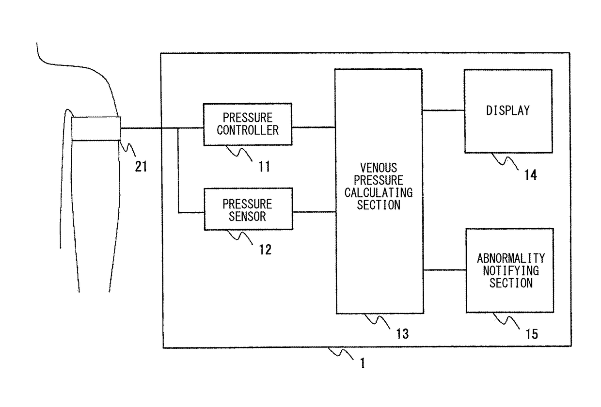
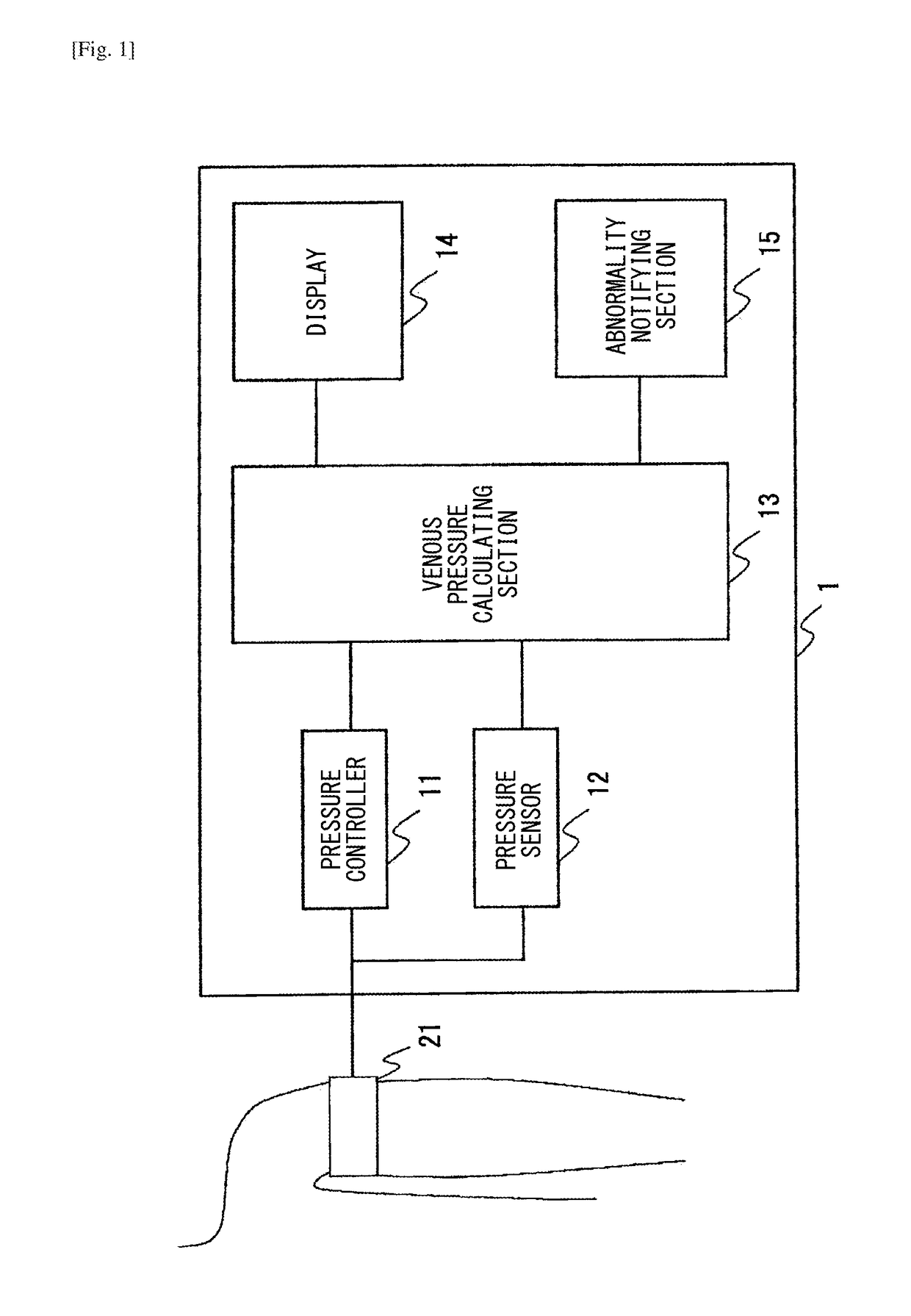
[0072]The configuration of the apparatus is not limited to the one illustrated in FIG. 1. FIG. 8 illustrates another example of the venous pressure measurement apparatus 1.

[0073]The venous pressure measurement apparatus 1 illustrated in FIG. 8 has, in addition to the configuration of FIG. 1, a configuration in which a probe 22 is attachable (like the the fourth exemplary embodiment of JP5694032B2). For example, the probe 22 is a usual probe for measuring the arterial oxygen saturation (SpO2).

[0074]The probe 22 detects a photoplethysmogram which is referred in the calculation of the venous pressure. ...

sixth embodiment

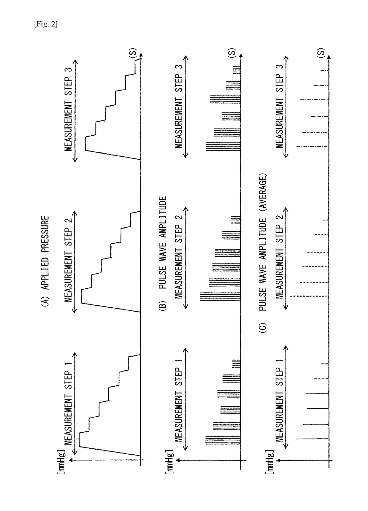
[0076]Alternatively, the venous pressure calculating section 13 may calculate the venous pressure by using a reference pulse wave and the pulse waves which are detected by the pressure sensor 12. That is, the venous pressure calculating section 13 may calculate the venous pressure based on a correlation between the reference pulse wave and the pulse wave as disclosed in paragraphs 0079 to 0085 of JP5694032B2 (JP5694032B2). Specifically, a pulse wave which is detected when the pressure applied by the cuff 21 is maximum is previously stored as the reference pulse wave. Thereafter, the pressure controller 11 changes the applied pressure as described above, and the pressure sensor 12 detects pulse waves in the measurement steps. The venous pressure calculating section 13 presumes the applied pressure at the timing when the correlation between the pulse wave (corresponding to the first pulse wave in JP5694032B2) detected by the pressure sensor 12 and the reference pulse wave is minimum, ...


PUM


Abstract

A venous pressure measurement apparatus includes a pressure controller configured to change a pressure applied from a cuff to a portion of a body where a vein and an artery exist and to which the cuff is attached, a pulse wave detector configured to detect pulse waves from a pressure the cuff receives from the portion of the body, and a venous pressure calculating section configured to calculate a venous pressure based on the applied pressure and the pulse waves detected by the pulse wave detector during a period in which the applied pressure is changed. The pressure controller is configured to execute a plurality of measurement steps, the applied pressure being increased or reduced from an initial value in each of the measurement steps.

Description

TECHNICAL FIELD[0001]The presently disclosed subject matter relates to an apparatus and method for measuring a venous pressure.BACKGROUND ART[0002]A venous pressure near a right atrium, so-called a central venous pressure, indicates a cardiac preload, and is an important index for monitoring circulatory dynamics. The central venous pressure can be invasively measured by inserting a catheter into a region rear the right atrium. Recently, a venous pressure measurement apparatus that can measure the central venous pressure by non-invasive means has been developed to reduce a burden on a subject.[0003]According to a first related art, a venous pressure measurement method includes temporarily congesting a vein and detecting a venous pressure from an image formed by a transmission of near infrared rays at the time when venous blood restarts to flow from the congested state (see, e.g., JP2010-279654A). With this method, however, because the venous pressure is measured at the time when the ...

Claims


Application Information

Patent Timeline
IPC IPC(8): A61B5/021
CPCA61B5/02116A61B5/02141A61B5/0225A61B5/7203A61B5/7246A61B5/02422A61B17/1355A61B2017/00119
Inventor UKAWA, TEIJIMORIMOTO, HARUKA
Owner NIHON KOHDEN CORP
Features
  • Generate Ideas
  • Intellectual Property
  • Life Sciences
  • Materials
  • Tech Scout
  • Unparalleled Data Quality
  • Higher Quality Content
  • 60% Fewer Hallucinations
Learn More