Mapping a Dig Site Diagram

a dig site and diagram technology, applied in the field of mapping a dig site, can solve the problems of prolonging the duration of excavation projects, insufficient labor force skilled enough to meet the demand for operating these vehicles, and high cost of excavation vehicles, so as to reduce the cost of excavation, reduce the need for manual labor, and increase the efficiency of excavation projects

Active Publication Date: 2018-07-26
BUILT ROBOTICS INC
View PDF8 Cites 39 Cited by
  • Summary
  • Abstract
  • Description
  • Claims
  • Application Information

AI Technical Summary

Benefits of technology

[0007]The described excavation system reduces the cost of excavating a site by reducing the need for manual labor, by obtaining actionable information that helps design and increase the efficiency of the excavation project, and by improving the overall quality and precision of the project by carrying out consistent, repeatable actions in accordance with excavation plans.

Problems solved by technology

Currently, operation of these excavation vehicles is very expensive as each vehicle requires a manual operator be available and present during the entire excavation.
Further complicating the field, there is an insufficient labor force skilled enough to meet the demand for operating these vehicles.
Because they must be operated manually, excavation can only be performed during the day, extending the duration of excavation projects and further increasing overall costs.
The dependence of current excavation vehicles on manual operators increases the risk of human error during excavations and reduce the quality of work done at the site.

Method used


Image

  • Mapping a Dig Site Diagram
  • Mapping a Dig Site Diagram
  • Mapping a Dig Site Diagram

Examples


Embodiment Construction

I. Excavation System

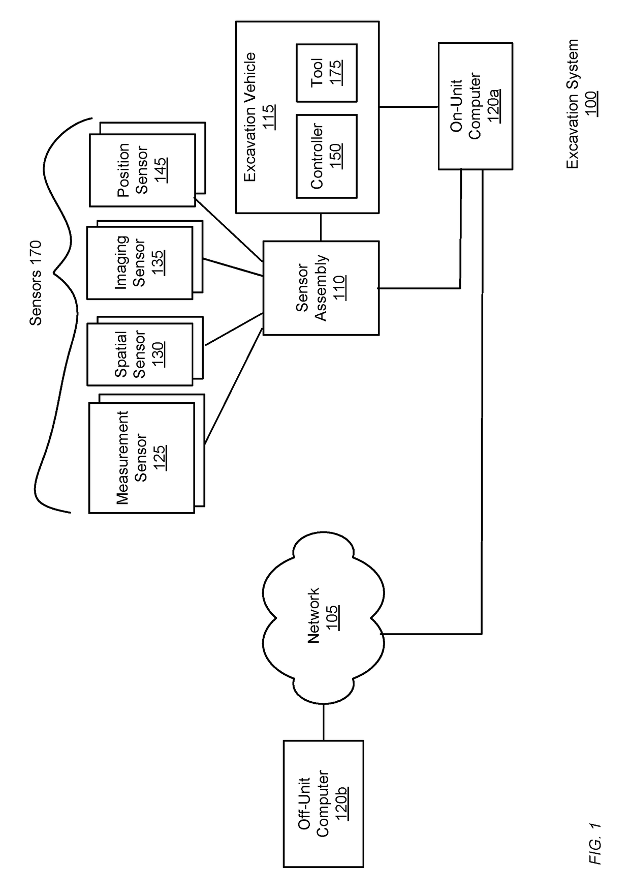
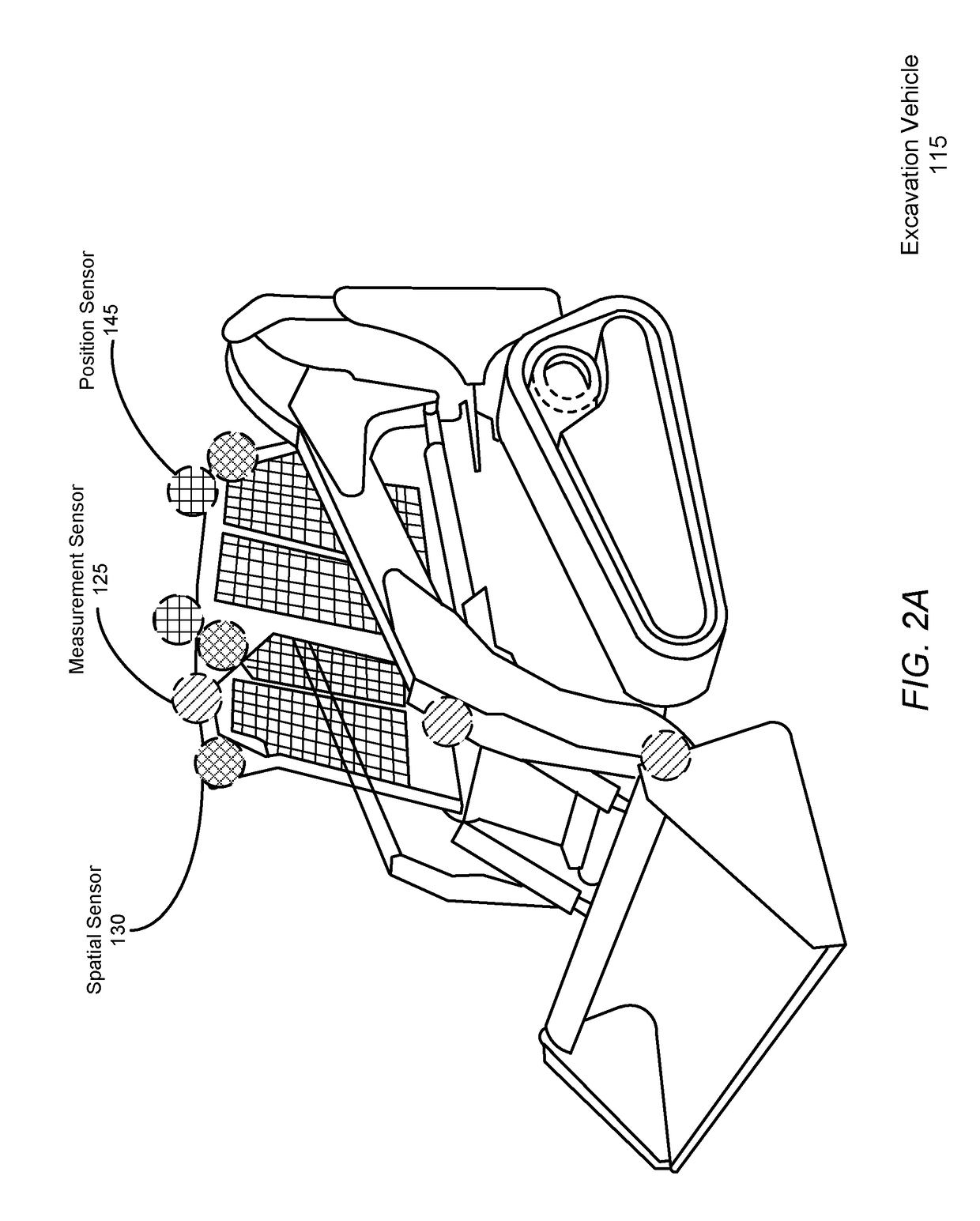
[0024]FIG. 1 shows an excavation system 100 for excavating earth autonomously or semi-autonomously from a dig site using a suite of one or more sensors 170 mounted on an excavation vehicle 115 to record data describing the state of the excavation vehicle 115 and the excavated site. As examples, FIGS. 2A and 2B illustrate the example placement of sensors for a compact track loader and an excavator, respectively, according to example embodiments. FIGS. 1-2B are discussed together in the following section for clarity.

[0025]The excavation system 100 includes a set of components physically coupled to the excavation vehicle 115. These include a sensor assembly 110, the excavation vehicle 115 itself, a digital or analog electrical controller 150, and an on-unit computer 120a. The sensor assembly 110 includes one or more of any of the following types of sensors: measurement sensors 125, spatial sensors 130, imaging sensors 135, and position sensors 145.

[0026]Each of thes...


PUM

PropertyMeasurementUnit
distancesaaaaaaaaaa
distancesaaaaaaaaaa
depthaaaaaaaaaa

Abstract

This description provides an autonomous or semi-autonomous excavation vehicle that is capable of navigating through a dig site and carrying out an excavation routine using a system of sensors physically mounted to the excavation vehicle. The sensors collects any one or more of spatial, imaging, measurement, and location data representing the status of the excavation vehicle and its surrounding environment. Based on the collected data, the excavation vehicle executes instructions to carry out an excavation routine. The excavation vehicle is also able to carry out numerous other tasks, such as checking the volume of excavated earth in an excavation tool, and helping prepare a digital terrain model of the site as part of a process for creating the excavation routine.

Description

BACKGROUNDField of Art[0001]The disclosure relates generally to method for excavating earth from a dig site, and more specifically to excavating earth using a vehicle operated using a sensor assembly coupled to control the vehicle.Description of the Related Art[0002]Vehicles such as backhoes, loaders, and excavators, generally categorized as excavation vehicles, are used to excavate earth from locations. Currently, operation of these excavation vehicles is very expensive as each vehicle requires a manual operator be available and present during the entire excavation. Further complicating the field, there is an insufficient labor force skilled enough to meet the demand for operating these vehicles. Because they must be operated manually, excavation can only be performed during the day, extending the duration of excavation projects and further increasing overall costs. The dependence of current excavation vehicles on manual operators increases the risk of human error during excavation...

Claims


Application Information

Patent Timeline
Patent Type & Authority Applications(United States)
IPC IPC(8): G05D1/02G01C21/20G01N33/24G05D1/00G06T7/73G06K9/00G06T17/05
CPCG05D1/0274G01C21/20G01N33/24G05D1/0088G05D1/0219G05D1/0231G06T7/74G06K9/00791G06T17/05G05D2201/0202G06T2207/30248E02F3/964E02F9/262E02F9/265E02F3/434E02F3/439E02F9/2029E02F9/205E02F9/2045G06V20/56E02F3/435E02F3/32
Inventor READY-CAMPBELL, NOAH AUSTENLIANG, ANDREW XIAOCHOU, LINUS PAGEWALKER, JR., EDWARD STEPHENWAWRZONEK, CHRISTIAN JOHNREADY-CAMPBELL, CYRUS MCMANN
Owner BUILT ROBOTICS INC
Why Eureka
Try Eureka