Power Module

a power module and power technology, applied in the field of power modules, can solve the problems of deteriorating heat dissipation performance, and achieve the effect of reducing the total thickness of the insulating layer and more heat dissipation

Active Publication Date: 2018-07-26
HITACHI ASTEMO LTD
View PDF1 Cites 8 Cited by
  • Summary
  • Abstract
  • Description
  • Claims
  • Application Information

AI Technical Summary

Benefits of technology

[0008]According to the present invention, the total thickness of the insulating layer can be reduced, and the power module is enabled to dissipate heat more. Therefore, an electric-power converting device can be downsized.

Problems solved by technology

However, if the voltage to be converted is high, the insulating material has to be formed to be thick in order to improve insulating performance, and heat dissipation performance is deteriorated.

Method used


Image

  • Power Module
  • Power Module
  • Power Module

Examples


first embodiment

[0038]First, a configuration of a power module will be described by using FIG. 1 to FIG. 3.

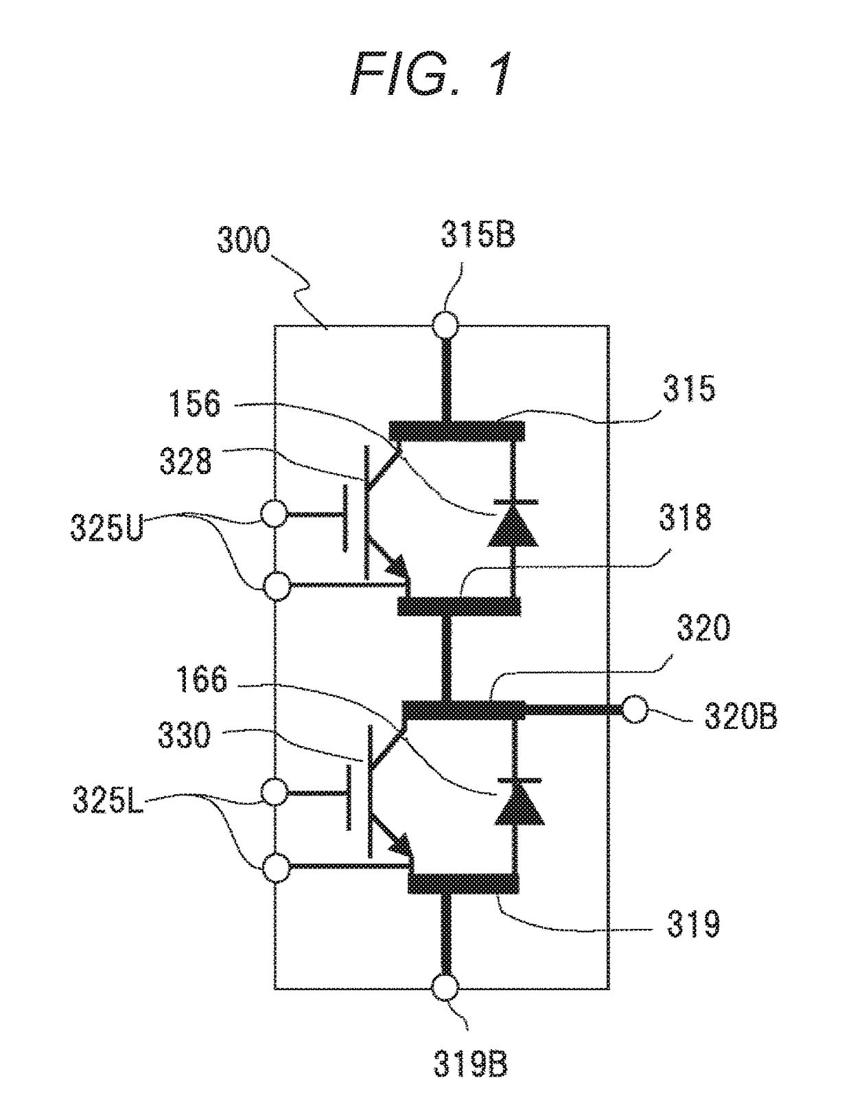
[0039]FIG. 1 is a circuit configuration diagram of a power module 300 of the present embodiment. The power module 300 includes an IGBT 328 and a diode 156, which constitute an upper arm circuit, and an IGBT 330 and a diode 166, which constitute a lower arm circuit. Herein, IGBT is an abbreviation of an insulated-gate-type bipolar transistor. A circuit which is connected to a positive electrode side of a battery and creates alternating-current waveforms by switching of a power semiconductor element is an upper arm circuit, and a circuit which is connected to a negative electrode side or GND side of the battery and creates alternating-current waveforms is a lower arm circuit. When neutral grounding is to be carried out, the lower arm circuit is connected to a negative electrode side of a capacitor instead of GND.

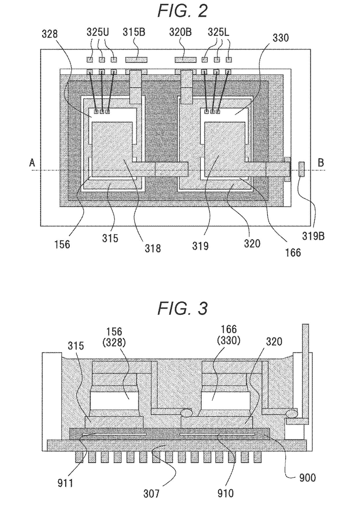
[0040]The power module 300 is provided with conductor plates 315, 318, 320, and 319...

third embodiment

[0095]A power module will be described by using FIG. 16 to FIG. 20.

[0096]FIG. 16 (a) is a perspective view of the power module of the present embodiment, and FIG. 16 (b) is a cross-sectional view of a section by a cross section E-F of FIG. 16 (a). The power module 300 of the present embodiment has a both-side cooling structure in which a power semiconductor element is housed in a cooling body 304, which is a CAN-type cooler. The cooling body 304 has a first heat dissipating surface 307A and a second heat dissipating surface 307B on which heat dissipating fins 305 are formed, thin portions 304A which connect heat dissipating surfaces and a frame body, and a flange portion 304B. A circuit body including the power semiconductor element and conductor plates is inserted from an insertion opening 306 of a cooling body 304, which is formed in a bottomed tubular shape, and is sealed by a sealing material 351, thereby forming the power module 300. The power module of the present embodiment ...

fourth embodiment

[0105]A power module will be described by using FIG. 21.

[0106]FIG. 21 is a cross-sectional view of the power module of the present embodiment. This corresponds to FIG. 17 about the power module of the third embodiment. A point changed from the third embodiment is that the number of intermediate conductors is increased.

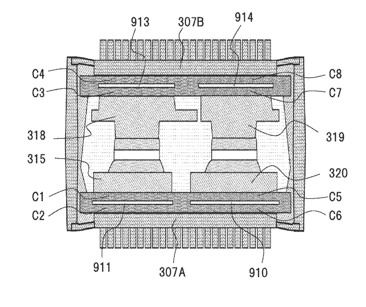
[0107]Intermediate conductors 910a and 910b are disposed between the conductor plate 320 and the heat dissipating surface 307A to which an alternating-current voltage is applied. Intermediate conductors 911a and 911b are disposed between the conductor plate 315 and the heat dissipating surface 307A to which a direct-current voltage is applied. Intermediate conductors 913a and 913b are disposed between the conductor plate 318 and the heat dissipating surface 307B to which an alternating-current voltage is applied. Intermediate conductors 914a and 914b are disposed between the conductor plate 319 and the heat dissipating surface 307B to which a direct-current voltage is...


PUM


Abstract

It is an object of the present invention to provide a power module which can withstand a high voltage with a thin insulating layer. A power module of the present invention is provided with a first power semiconductor element 328 of an upper arm side constituting an inverter circuit, a second power semiconductor element 330 of a lower arm side, a first conductor part 320 which transmits an alternating current, a second conductor part 315 which transmits a direct current, an electrically-conductive heat dissipating part 307, a first intermediate conductor layer 910 disposed between the first conductor part 320 and the heat dissipating part 307 via an insulating layer 900, and a second intermediate conductor layer 911 disposed between the second conductor part 315 and the heat dissipating part 307 via the insulating layer 900, wherein, the second intermediate conductor layer 911 is formed to be separated from the first intermediate conductor layer 910, and the first intermediate conductor layer 910 forms a capacity circuit which shares the voltage between the first conductor part 320 and the heat dissipating part 307.

Description

TECHNICAL FIELD[0001]The present invention relates to a power module in which power semiconductor elements are made into a module and particularly relates to a power module to be mounted in a vehicle.BACKGROUND ART[0002]Since electric-power converting devices using switching of power semiconductor elements have high conversion efficiency, the electric-power converting devices are widely utilized for commercial uses, mounting in cars, railroads, electric transformation equipment, etc. Since this power semiconductor element generates heat when electricity is distributed, high heat dissipation performance is required. Normally, in heat dissipation, a metal-made heat dissipating structure having fins is used, and it is grounded to the ground (GND) in order to stabilize electric potentials and to prevent electric shock. Therefore, an insulating material disposed between the power semiconductor element and the heat dissipating structure is required to have excellent thermal conductivity. ...

Claims


Application Information

Patent Timeline
Patent Type & Authority Applications(United States)
IPC IPC(8): H01L25/07H01L23/367H01L23/373H01L23/495H02M7/00H02M7/537
CPCH01L25/072H01L23/3677H01L23/3735H01L23/49575H02M7/003H02M7/537H01L25/18H01L2924/181H01L24/40H01L2224/32225H01L2224/48091H01L2224/48137H01L2224/48227H01L2224/4911H01L2224/49171H01L2224/49175H01L2224/73265H01L2924/19107H01L2224/05554H01L2224/04034H01L2224/04042H01L2224/33H01L2924/1203H01L2924/13055H01L2924/00014H01L2224/37599H01L23/367H01L23/5385H01L24/37H01L2224/49177H01L2224/33181H01L2924/13091H01L2224/40139H01L2224/40137H01L2224/0603H01L24/97H01L2924/00012H01L2924/00H01L2224/37099H01L2224/45099H01L2224/84H01L2224/73221
Inventor TSUYUNO, NOBUTAKEKUSUKAWA, JUNPEITOKUYAMA, TAKESHISUWA, TOKIHITO
Owner HITACHI ASTEMO LTD
Why Eureka
Try Eureka