Thermally Highly Conductive Coating on Base Structure Accommodating a Component

a technology of component carrier and base structure, which is applied in the direction of solid-state device, semiconductor/solid-state device details, printed circuit assembling, etc., can solve the problems of increasing the heat generated by such components and the component carrier itself during operation, and affecting the operation efficiency of the component carrier

Active Publication Date: 2018-07-26
AT & S CHINA
View PDF33 Cites 11 Cited by
  • Summary
  • Abstract
  • Description
  • Claims
  • Application Information

AI Technical Summary

Benefits of technology

[0005]There may be a need to embed a component in a compo...

Problems solved by technology

Removal of heat generated by such components and the component carrier itself during operation becomes an increasing issue.
Moreover, embedding a component in a component carrier ...

Method used


Image

  • Thermally Highly Conductive Coating on Base Structure Accommodating a Component
  • Thermally Highly Conductive Coating on Base Structure Accommodating a Component
  • Thermally Highly Conductive Coating on Base Structure Accommodating a Component

Examples


Embodiment Construction

[0008]In the context of the present application, the term “component carrier” may particularly denote any support structure which is capable of accommodating one or more components thereon and / or therein for providing mechanical support and / or electrical connectivity. In other words, a component carrier may be configured as a mechanical and / or electronic carrier for components. In particular, a component carrier may be one of a printed circuit board, an organic interposer, and an IC (integrated circuit) substrate. A component carrier may also be a hybrid board combining different ones of the above mentioned types of component carriers.

[0009]In the context of the present application, the term “thermally highly conductive coating” may particularly denote a layer-type rather than a bulky structure with a thickness being smaller than the thickness of the entire component carrier. For instance, the thickness of the coating may be less than 50%, in particular smaller than 30%, more partic...


PUM


Abstract

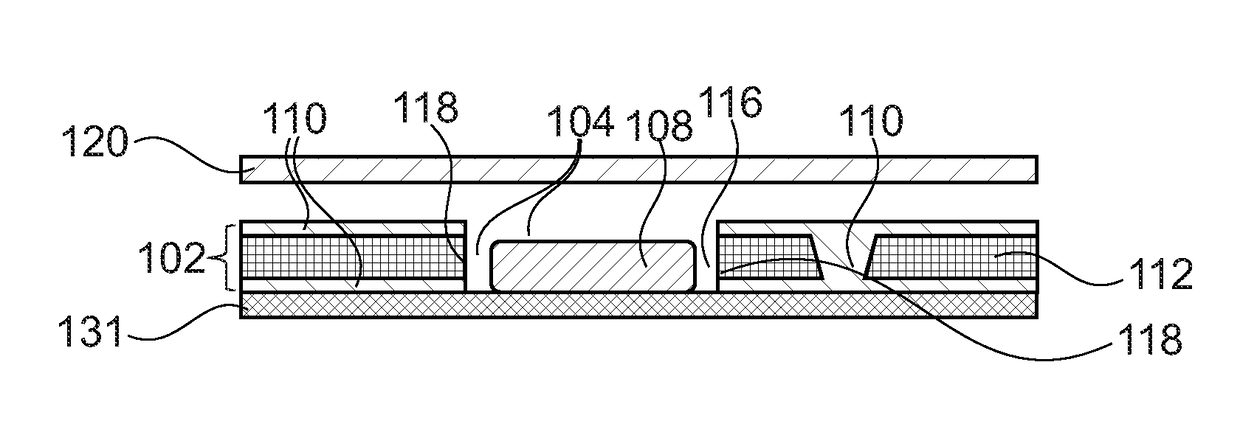
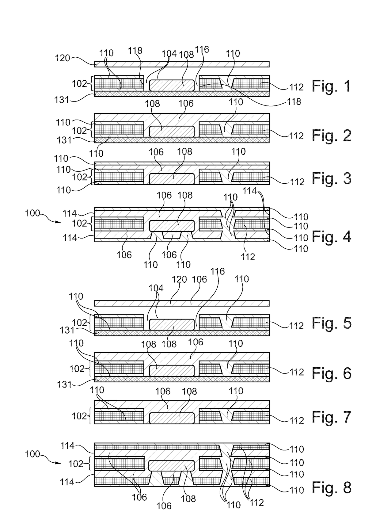
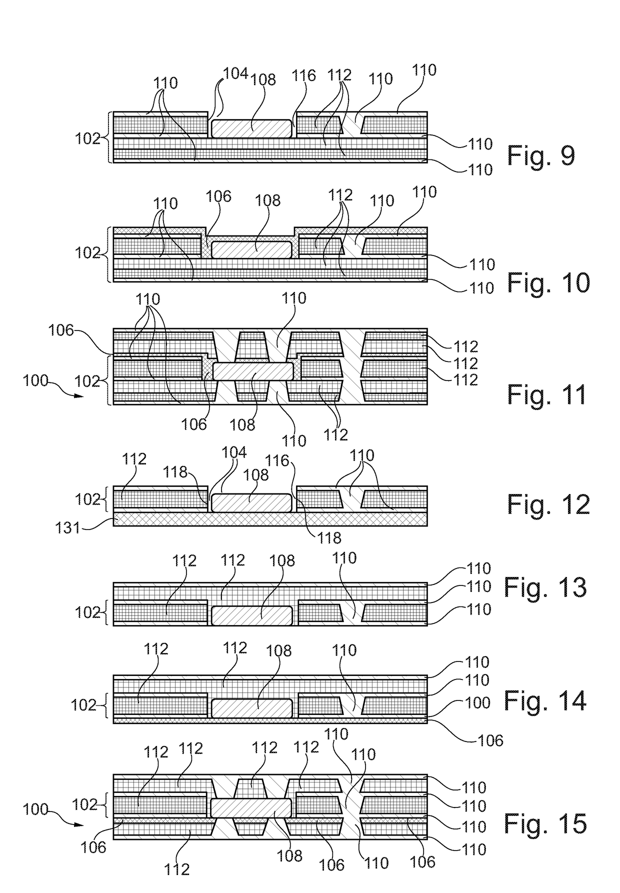
A component carrier has a base structure with a recess, a thermally highly conductive coating covering at least a part of a surface of the base structure, and a component in the recess.

Description

CROSS-REFERENCE TO RELATED APPLICATION[0001]This application claims the benefit of the filing date of the Chinese Patent Application No. 2017-10061261.8 filed 25 Jan. 2017, the disclosure of which is hereby incorporated herein by reference.TECHNICAL FIELD[0002]The invention relates to a method of manufacturing a component carrier, and to a component carrier.BACKGROUND[0003]In the context of growing product functionalities of component carriers equipped with one or more electronic components and increasing miniaturization of such components as well as a rising number of components to be mounted on the component carriers such as printed circuit boards, increasingly more powerful array-like components or packages having several components are being employed, which have a plurality of contacts or connections, with ever smaller spacing between these contacts. Removal of heat generated by such components and the component carrier itself during operation becomes an increasing issue. At the...

Claims


Application Information

Patent Timeline
IPC IPC(8): H05K1/02H05K7/20H01L23/373H01L23/00
CPCH05K1/0201H05K7/20H01L23/373H01L24/20H01L23/3735H01L23/42H05K1/0203H05K1/185H05K3/30H05K2201/06H01L21/56H01L23/3121H01L23/3737H01L23/5389H01L24/19H01L2224/04105H01L2224/18H01L2224/2518H01L2224/92144H01L2924/0001
Inventor TUOMINEN, MIKAELTAY, ANNIEBAFTIRI, ARTAN
Owner AT & S CHINA
Why Eureka
Try Eureka