

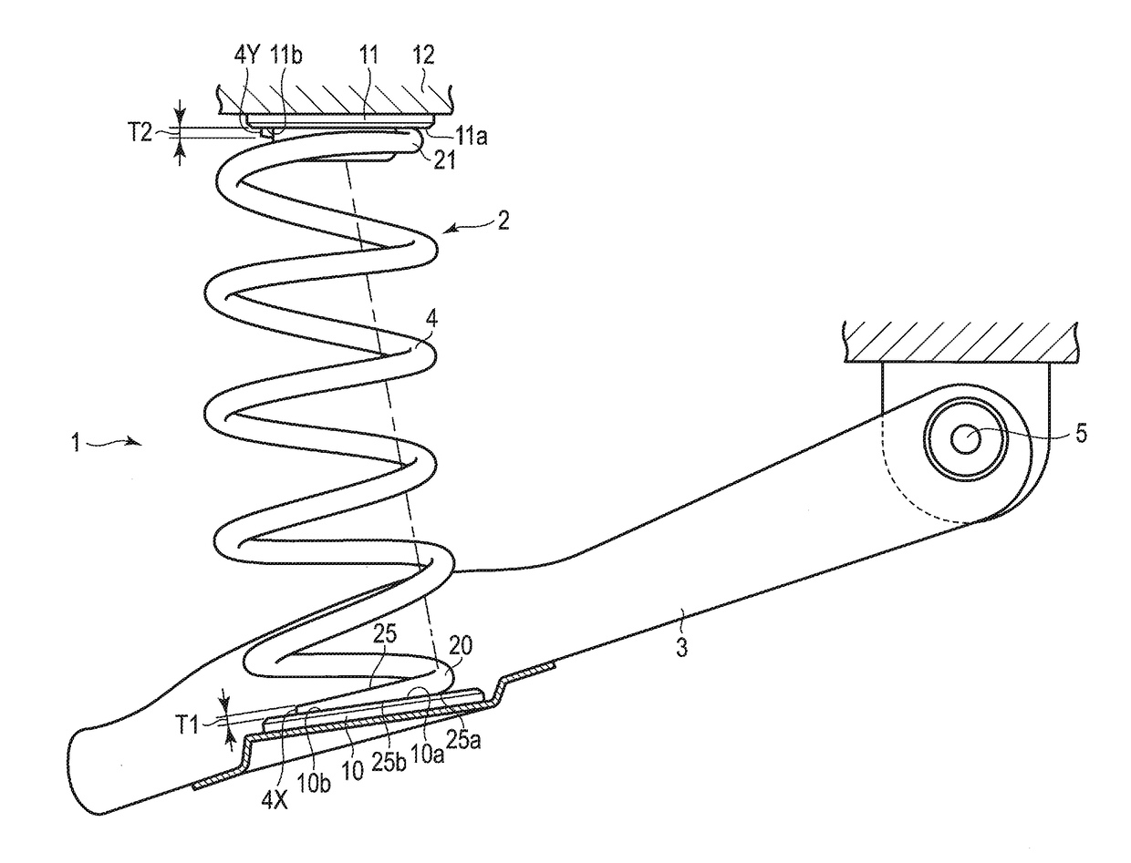
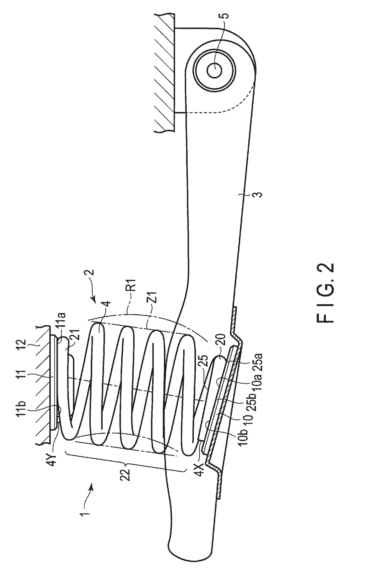
Coil spring for vehicle suspension
a vehicle suspension and coil spring technology, applied in the direction of coil springs, mechanical equipment, transportation and packaging, etc., can solve the problem of difficult formation of plastic working parts, and achieve the effect of reducing stress amplitud
- Summary
- Abstract
- Description
- Claims
- Application Information
AI Technical Summary
Benefits of technology
Problems solved by technology
Method used
Image

Examples
second embodiment
[0049]FIG. 11 shows a taper portion 26′ of a round tapered shape formed at the end of a wire 4 of a coil spring according to a FIG. 12 is a front view of the taper portion 26′ as seen from a distal end 4Y. In the taper portion 26′, the diameter of the wire 4 is gradually reduced from a thickness varying portion 26a′ toward the distal end 4Y of the wire 4 so that the wire 4 is evenly reduced in a tapered way.
[0050]The round tapered taper portion 26′ has a rotationally symmetric shape about the axis of the wire 4. When forming a coil spring by the hot forming coiling machine 30 (FIG. 10), the end turn portion on the winding end side should preferably be formed as the round tapered taper portion 26′. The reason for this is that it is difficult to accurately control the position of the end turn portion on the winding end side because the wire 4 is twisted about the axis during coiling. Therefore, by adopting the round tapered taper portion 26′ at the end turn portion on the winding end...
third embodiment
[0051]FIG. 13 shows a taper portion 25′ of a wire 4 of a coil spring according to a FIG. 14 shows a cross section of the taper portion 25′ shown in FIG. 13. By polishing or grinding an end face of an end portion of the wire 4 obtained after coiling by a grinder, etc., the taper portion 25′ of a type whose end face is polished is formed. The thickness of the taper portion 25′ is reduced in a tapered way from a thickness varying portion 25a′ toward a distal end 4X of the wire 4. In the case of a cold formed coil spring, after coiling the wire, the taper portion 25′ of the type whose end face is polished can be formed.
PUM
 Abstract
Description
Claims
Application Information