Refrigeration device and container refrigeration system

Inactive Publication Date: 2018-08-09
DENSO CORP
View PDF2 Cites 30 Cited by
  • Summary
  • Abstract
  • Description
  • Claims
  • Application Information

AI Technical Summary

Benefits of technology

[0017]The container refrigeration system in the present disclosure includes the electric compressor in which a discharge amount of refrigerant is controlled by the inverter device to which the AC output from the power generator is supplied. Therefore, a rotation speed of the electric compressor can be changed in a wide range regardless of a rotation speed of the engine. Conse

Problems solved by technology

Therefore, especially in a North American trailer as long as 53 feet, a short circui

Method used


Image

  • Refrigeration device and container refrigeration system
  • Refrigeration device and container refrigeration system
  • Refrigeration device and container refrigeration system

Examples


first embodiment

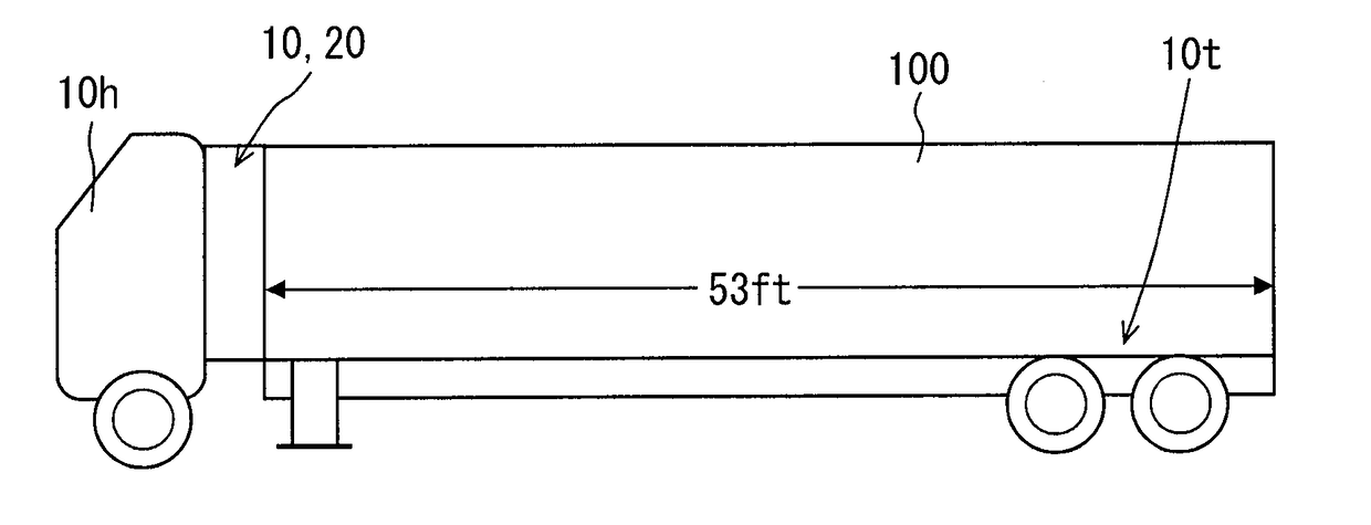
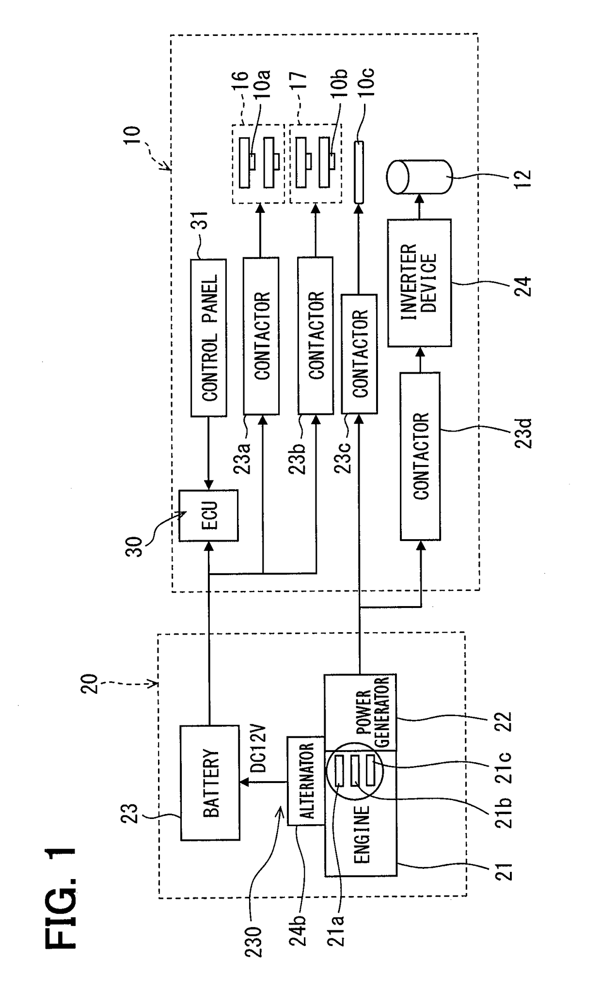
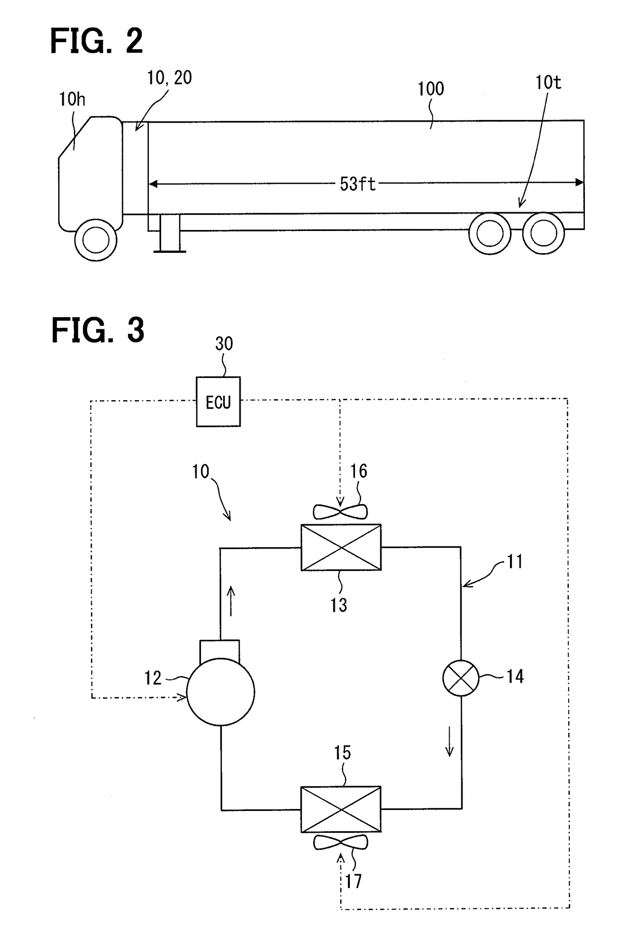
[0028]A first embodiment of the present disclosure will be described below by using FIGS. 1 to 6. FIG. 1 shows an overall configuration of a container refrigeration system according to the first embodiment. In the first embodiment, the container refrigeration system includes an electricity generating unit 20 and a refrigeration device 10. FIG. 2 shows an outline of a vehicle and FIG. 3 shows a configuration of a refrigeration cycle of the refrigeration device 10.

[0029]As shown in FIG. 3, the refrigeration device 10 in the present embodiment includes an electric compressor 12, a condenser 13, an evaporator 15, a condenser fan 16, and an evaporator fan 17. The condenser fan 16 is driven by a DC output from a DC power supply device 230 and blows air to the condenser 13. The evaporator fan 17 is driven by the DC output from the DC power supply device 230 and blows air to the evaporator 15. A controller 30 controls the electric compressor 12, the condenser fan 16, and the evaporator fan ...

second embodiment

[0075]Next, a second embodiment of the present disclosure will be described with reference to FIG. 7.

[0076]In FIG. 7, a power generator 22 that is driven by an engine 21 outputs three-phase 400V AC voltage. The AC voltage output by the power generator 22 is led to an AC-DC converter (simply referred to as “converter” as well) 24a. The converter 24a in place of the alternator 24b in FIG. 1 outputs 12V DC voltage to charge a battery 23. The 12V DC voltage output from the battery 23 is led to the controller 30. The 12V DC voltage is led to a condenser motor 10a and an evaporator fan motor 10b for driving a condenser fan 16 and an evaporator fan 17 via a contactor 23a for the condenser motor 10a and a contactor 23b for the evaporator fan motor 10b, respectively.

[0077]A DC power supply device 230 that is powered by the engine 21 to generate a DC output includes the converter 24a and the battery 23. The three-phase 400V AC voltage output by the power generator is converted into arbitrary ...


PUM


Abstract

The refrigeration device has an inverter device, an electric compressor, a condenser, an evaporator, a condenser fan, an evaporator fan, and a controller. An AC output from a power generator is supplied to the inverter device. A refrigerant discharge amount of the electric compressor is controlled by the inverter device. The refrigerant from the electric compressor flows in the condenser, and the condenser causes the refrigerant to radiate heat to outside air outside a container. The refrigerant from the condenser flows in the evaporator, and the evaporator cools an interior of the container. The condenser fan is driven by a DC output from a DC power supply device and blows air to the condenser. The evaporator fan is driven by the DC output from the DC power supply device and blows air to the evaporator. The controller controls at least the electric compressor, the inverter device, and the engine.

Description

CROSS REFERENCE TO RELATED APPLICATION[0001]This application is based on Japanese Patent Application No. 2014-183588 filed on Sep. 9, 2014, the disclosure of which is incorporated herein by reference.TECHNICAL FIELD[0002]The present disclosure relates to a refrigeration device that cools an interior of a container and a container refrigeration system that has the refrigeration device and a power generator.BACKGROUND ART[0003]A trailer having a container refrigeration system, in which the system uses electric power generated by a power generator to drive a refrigeration device, has been in practical use. The refrigeration device of the trailer does not include an inverter but includes an electric compressor driven by use of a three-phase induction motor. A blower such as a condenser fan motor in the refrigeration device is also driven by the same three-phase output. However, in this refrigeration device, the electric compressor and the blower can be driven only by an AC power supply ...

Claims


Application Information

Patent Timeline
IPC IPC(8): B60H1/00B60H1/22B60H1/32
CPCB60H1/00364B60H1/0045B60H1/2215B60H1/3205B60H1/3208B60H1/3222B60H2001/3238B60H2001/3273H02P27/06B60H1/00428F25B27/00F25B49/025F25B2600/021F25B2600/111F25B2600/112F25D11/00Y02T10/88Y02B30/70
Inventor MIZUMA, IKUO
Owner DENSO CORP
Why Eureka
Try Eureka