Supercharge Your Innovation With Domain-Expert AI Agents!

Electrolyzed water production device, electrolyzed water production method, and electrolytic bath

a technology of electrolysis water and electrolysis bath, which is applied in the direction of specific water treatment objectives, water/sewage treatment by oxidation, water treatment compounds, etc., can solve the problems of complex connection between the electrolytic bath and various flexible pipes or connecting terminals, the connection points may not be appropriately fitted, and etc., to achieve the effect of reducing the concern about the leakage facilitating the handling of the electrolytic bath, and reducing the leakag

Inactive Publication Date: 2018-08-09
MORINAGA MILK IND CO LTD
View PDF2 Cites 0 Cited by
  • Summary
  • Abstract
  • Description
  • Claims
  • Application Information

AI Technical Summary

Benefits of technology

The invention provides a way to electrolyze water using a sealed electrolytic bath that can be easily mounted and has a simplified structure. The electrolyzed water can be produced in a subdivided manner by using a predetermined amount of raw material solution. The service life of the electrolytic bath can be extended by applying a current multiple times to perform multiple rounds of electrolysis on the same amount of raw material solution. This reduces the replacement frequency of the electrolytic bath and simplifies the production of electrolyzed water.

Problems solved by technology

However, the electrolyzed water production device described in Patent Document 1 requires the work of replacing the inside of the electrolytic bath with water during the replacement of the electrolytic bath.
Although this work does not pose problems to traders who handle the electrolyzed water production device, the work may become complicated for users for use in standard homes or for business use in small-to-medium-scale facilities.
Additionally, the connection between the electrolytic bath and various flexible pipes or the connecting terminals may be complicated and difficult.
Additionally, in the electrolyzed water production devices described in Patent Documents 2 to 6, there are many connection points between the electrolytic bath and the device body, and when the electrolytic bath is mounted on the device body, the connection points may not be appropriately fitted and may be damaged if the positional deviation of both of the electrolytic bath and the device body occurs.
Additionally, due to this, poor connection may occur or a failure may be caused.
Accordingly, although such handling does not pose problems to traders who handle the electrolytic bath, the handling of the electrolytic bath is not easy and is complicated for ordinary users.

Method used


Image

  • Electrolyzed water production device, electrolyzed water production method, and electrolytic bath
  • Electrolyzed water production device, electrolyzed water production method, and electrolytic bath
  • Electrolyzed water production device, electrolyzed water production method, and electrolytic bath

Examples


modification examples

[0263]Next, Modification Examples 1 to 9 of the above first embodiment will be described. In the description of these modification examples, the only parts that are different from those of the electrolyzed water production device 1A of the aforementioned first embodiment will be described, the same components will be designated by the same reference numerals, and the description thereof will be omitted.

[0264]As illustrated in FIG. 14, Modification Example 1 is different from the electrolyzed water production device 1A of the first embodiment in terms of a method of locking and fixing the electrolytic bath 3 when the insertion of the electrolytic bath 3 into a mounting section 6a is completed and is arranged at a predetermined installation position.

[0265]As a locking part of the present Modification Example 1, a slide cover 60 which is arranged to straddle the top wall 9 and the bottom wall 10 of the mounting section 6a is used instead of the locking parts 16A and 16B illustrated in ...

example 1

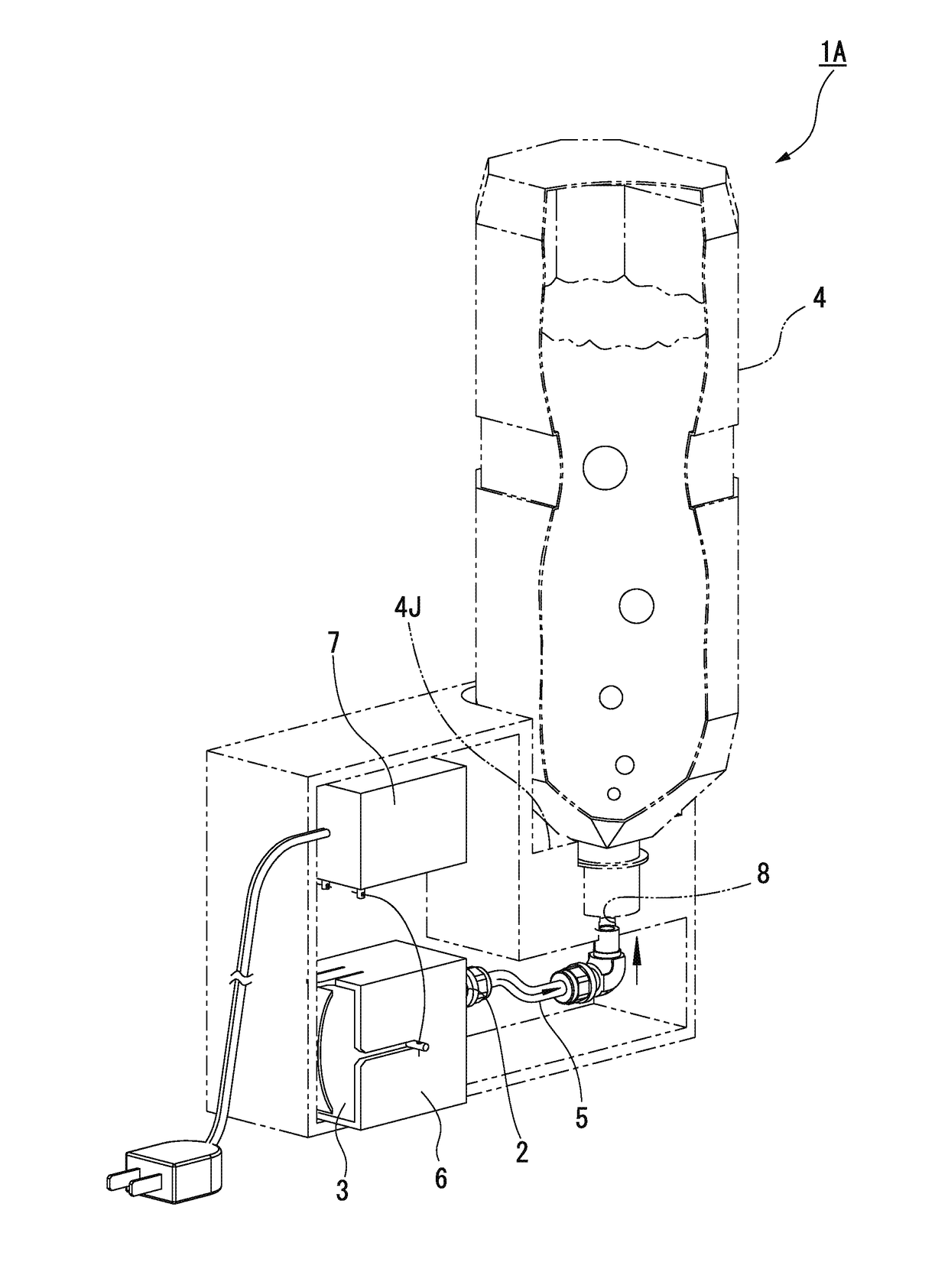
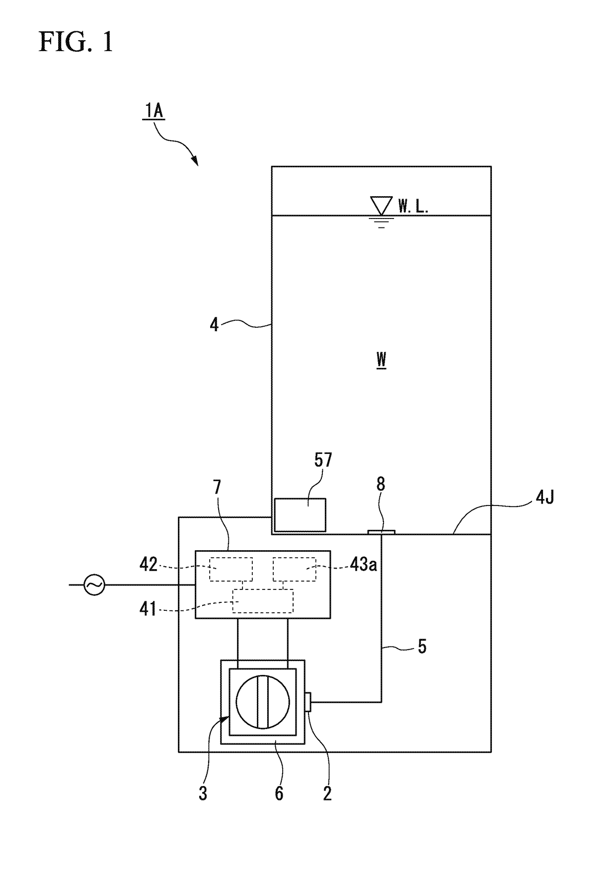
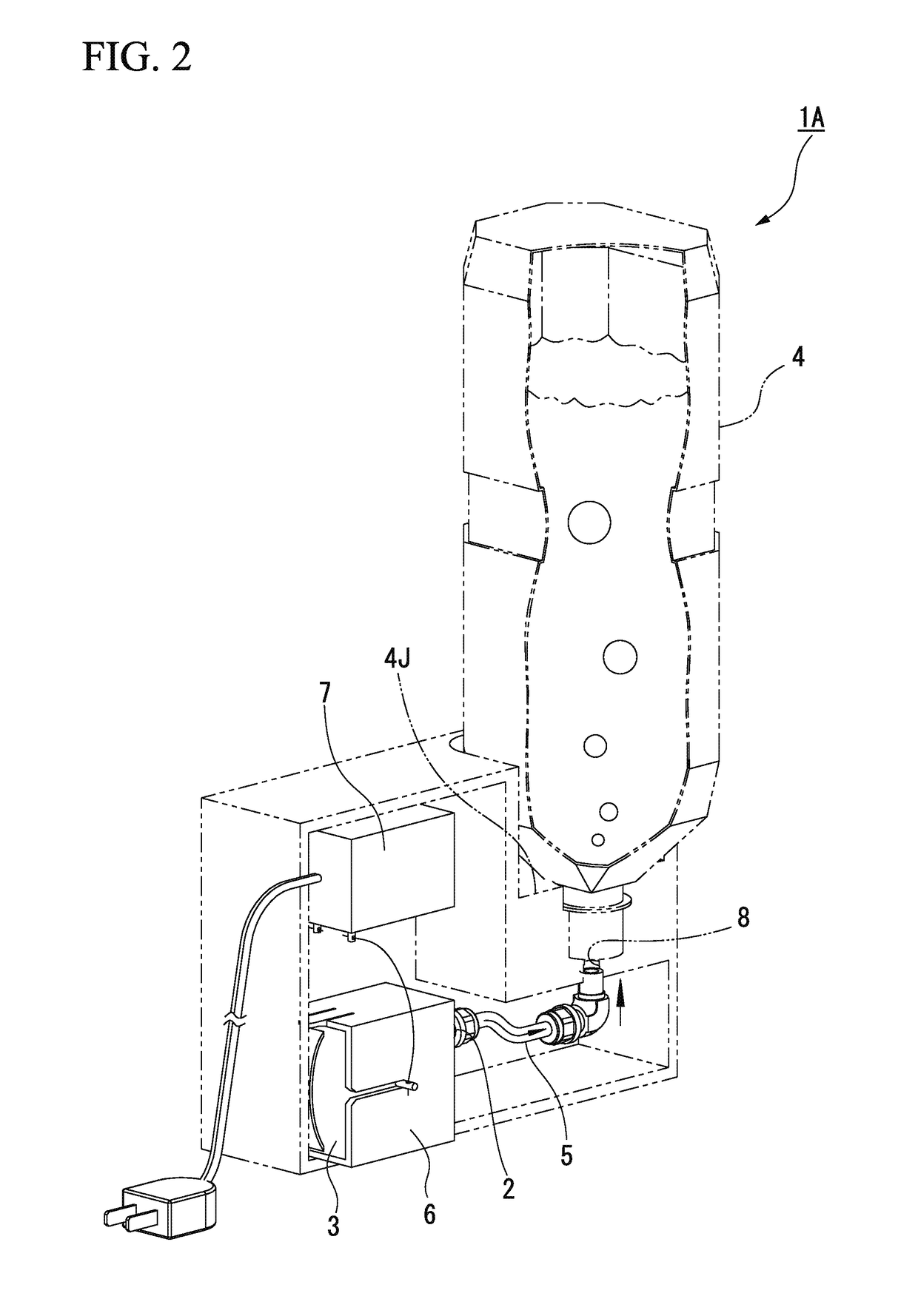
[0393](Electrolyzed Water Production Device)

[0394]In Example 1, as the electrolytic bath 3, a bath having a capacity of 52 ml and having nine unit cells C partitioned by ten electrode plates 31 was used. A PET bottle having a capacity of 2 liters was used as the tank 4. 3% of hydrochloric acid was enclosed in the electrolytic bath 3 as the dilute hydrochloric acid (raw material solution). The current efficiency of the electrolytic bath 3 is 50%. The current value was selectively set from 0.8 A, 1.6 A, and 2.4 A.

[0395](Electrolysis Method)

[0396]The electrolytic bath 3, which was filled with 3% of the dilute hydrochloric acid and was sealed, was mounted on the mounting section 6. 2 liters of tap water was put into the PET bottle, a backflow check valve was attached to an opening of the bottle, and the bottle was installed in the installation section 4J. In this state, a constant current of a predetermined current value was applied to the electrolytic bath 3, the dilute hydrochloric ac...

example 2

[0402](Electrolyzed Water Production Device)

[0403]In the present example, as the electrolytic bath 3, a bath having a capacity of 35 ml and having six unit cells C partitioned by seven electrode plates 31 was used. A tank having a capacity of 3 liters was used as the tank 4. 6% of hydrochloric acid was enclosed in the electrolytic bath 3 as the dilute hydrochloric acid (raw material solution). The current value was 2.5 A, and the unit time (electrolysis voltage application time) was selectively settable from 10 seconds, 20 seconds, and 30 seconds.

[0404](Electrolysis Method)

[0405]The electrolytic bath 3, which was filled with 3% of the dilute hydrochloric acid and was sealed, was mounted on the mounting section 6. 3 liters of tap water was put into the tank, and stirring was started by a submerged pump. The current value of 2.5 A was applied for a predetermined unit time so as to electrolyze the dilute hydrochloric acid. Since Electrolysis time [sec]=(Desired available chlorine conce...


PUM

PropertyMeasurementUnit
current efficiencyaaaaaaaaaa
electrolysis voltageaaaaaaaaaa
voltageaaaaaaaaaa

Abstract

This electrolyzed water production device (1A) includes an electrolytic bath (3) that discharges electrolyzed products generated by electrolysis of a raw material solution from an outlet (2); a mixing section (4) that mixes the electrolyzed products with dilution water to generate electrolyzed water; and a mounting section (6) that has a connecting section (19) where a hole section (20) connected to the outlet (2) is formed and that allows the electrolytic bath (3) to be detachably mounted thereto. By moving either the electrolytic bath (3) or the connecting section (6) relative to the other, the communication between the outlet (2) and the hole section (20) is allowed or released. Additionally, the electrolytic bath (3) is mounted on the mounting section (6) in a state where the inside of the electrolytic bath (3) is filled with a predetermined amount of the raw material solution and sealed in advance and an additional raw material solution cannot be injected thereinto.

Description

TECHNICAL FIELD[0001]The present invention relates to an electrolyzed water production device, an electrolyzed water production method, and an electrolytic bath that electrolyzes a raw material solution to produce electrolyzed water.[0002]Priority is claimed on Japanese Patent Application No. 2012-218855, filed Sep. 28, 2012, and Japanese Patent Application No. 2012-218856, filed Sep. 28, 2012, the contents of which are incorporated herein by reference.BACKGROUND ART[0003]In the related art, it is known that electrolyzed water, which is obtained by electrolyzing a raw material solution containing chlorine ions using an electrolyzed water production device, has a high disinfection effect even in the case of a low available chlorine concentration, and also has advantageous properties, such as having a high degree of safety for human beings. Such electrolyzed water is widely used for disinfection of food or instruments that process this food in food-related fields or the like. In recen...

Claims


Application Information

Patent Timeline
Patent Type & Authority Applications(United States)
IPC IPC(8): C02F1/461C02F1/467C02F1/76C25B1/26C25B9/00C25B15/02
CPCC25B1/26C02F1/76C02F2303/04C02F1/46109C02F1/4618C02F2001/46152C02F2305/00C02F2201/4615C25B9/00C02F2307/06C02F2307/04C25B15/02C02F1/4674C02F2001/46185
Inventor MATSUYAMA, KOKISHIRATO, MASAYASU
Owner MORINAGA MILK IND CO LTD
Features
  • R&D
  • Intellectual Property
  • Life Sciences
  • Materials
  • Tech Scout
  • Unparalleled Data Quality
  • Higher Quality Content
  • 60% Fewer Hallucinations
Learn More