Fuel injection control device and fuel injection control method for internal combustion engine

a control device and fuel injection technology, applied in the direction of electric control, machines/engines, mechanical equipment, etc., can solve the problems of unintentional reaches of the maximum value, noise, and lowering the learning accuracy of the injection characteristics, so as to reduce the detection accuracy of valve closing detection processing

Active Publication Date: 2018-08-09
TOYOTA JIDOSHA KK
View PDF1 Cites 6 Cited by
  • Summary
  • Abstract
  • Description
  • Claims
  • Application Information

AI Technical Summary

Benefits of technology

[0020]Even when the continuation time of the energization processing is the same, the injection amount increases when the pressure of the fuel is high compared to when it is low. Therefore, in order to provide the same injection amount of the partial lift injection processing according to the learning request, the continuation time of the energization processing becomes short when the pressure is high compared to when it is low. It has been found by the inventors that when the continuation time of the energization processing is excessively short, the detection accuracy by the valve closing detection processing is lowered. On the other hand, when the continuation time of the energization processing is excessively long, there is a possibility that the lift amount unintentionally reaches the maximum value. Therefore, in the above-described configuration, by increasing the injection amount of the partial lift injection processing, according to the learning request, when the pressure of the fuel is high compared to when it is low, the energization processing that is appropriate for learning can be executed regardless of the magnitude of the pressure.

Problems solved by technology

As a result, there is a possibility that the learning accuracy of the injection characteristics is lowered.
If the energization processing to the coil is executed for the other cylinder when the valve closing detection processing is executed, there is a possibility that noise caused by this is superimposed on a detection result of the terminal potential of the coil being the detection object or the current flowing through the coil being the detection object.
On the other hand, when the continuation time of the energization processing is excessively long, there is a possibility that the lift amount unintentionally reaches the maximum value.

Method used


Image

  • Fuel injection control device and fuel injection control method for internal combustion engine
  • Fuel injection control device and fuel injection control method for internal combustion engine
  • Fuel injection control device and fuel injection control method for internal combustion engine

Examples


Embodiment Construction

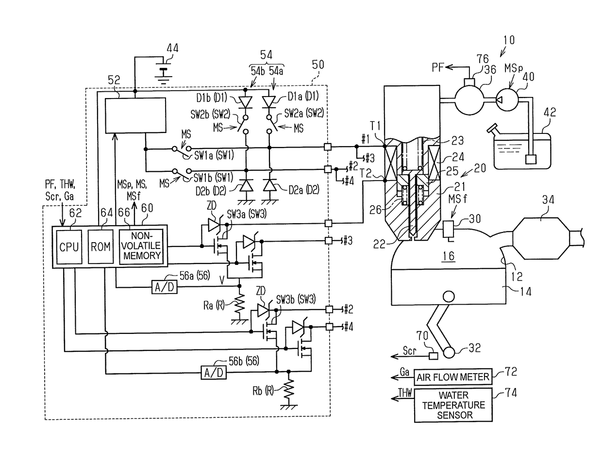
[0031]Hereinbelow, a fuel injection control device for an internal combustion engine according to an embodiment will be described with reference to the drawings. As shown in FIG. 1, a fuel injection valve 20 protrudes into a combustion chamber 16 defined by a cylinder 12 and a piston 14 of an internal combustion engine 10. In this embodiment, the internal combustion engine 10 is a four-cylinder internal combustion engine. In FIG. 1, only a first combustion cylinder #1 is shown, while an illustration of second, third, and fourth combustion cylinders #2, #3, and #4 is omitted. It is to be noted that the i-th combustion cylinder #i (i=1 to 4) represents the combustion cylinder in which the compression top dead center occurs at the i-th timing in a combustion cycle.

[0032]A nozzle needle 22 is housed in a hollow body 21 of the fuel injection valve 20. The nozzle needle 22 is biased in a valve closing direction by an elastic force of a spring 23. The fuel injection valve 20 includes a coi...


PUM


Abstract

During rapid warm-up operation, a CPU executes full lift injection processing, in which a nozzle needle reaches a maximum lift amount, in an intake stroke of each cylinder of a four-cylinder internal combustion engine, and then executes partial lift injection processing, in which the nozzle needle does not reach the maximum lift amount, in a compression stroke. On the other hand, during learning of injection characteristics of partial lift injection processing, the CPU executes full lift injection processing after executing partial lift injection processing, both of which are executed within a predetermined period in an intake stroke. The CPU learns the injection characteristics based on an inflection point in the temporal change of the induced electromotive force in a coil following the end of the partial lift injection processing.

Description

INCORPORATION BY REFERENCE[0001]The disclosure of Japanese Patent Application No. 2017-020715 filed on Feb. 7, 2017 including the specification, drawings and abstract is incorporated herein by reference in its entirety.BACKGROUND1. Technical Field[0002]The disclosure relates to a fuel injection control device and a fuel injection control method for an internal combustion engine in which a plurality of cylinders are respectively provided with fuel injection valves each configured to open when an electromagnetic force generated by energization of a coil acts on a movable element made of a magnetic body.2. Description of Related Art[0003]Japanese Patent Application Publication No. 2015-190318 (JP 2015-190318 A) describes a fuel injection control device that learns the injection characteristics of a fuel injection valve with respect to partial lift injection that opens the fuel injection valve in such a way that the lift amount of a nozzle needle does not reach a maximum lift amount. Th...

Claims


Application Information

Patent Timeline
Patent Type & Authority Applications(United States)
IPC IPC(8): F02D41/40F02D41/24
CPCF02D41/401F02D41/2441F02D41/26F02M61/10F02M51/061F02D41/38F02M61/161F02D41/20F02D41/2467F02D41/345F02D41/402F02D2041/2055F02D2041/2058F02D2200/063Y02T10/40
Inventor NAKANO, TOMOHIRO
Owner TOYOTA JIDOSHA KK
Why Eureka
Try Eureka