
Continuous low oxygen and high temperature combustion aluminum melting furnace with porous injection pipe heat exchanger

a technology of high-temperature combustion and aluminum melting furnace, which is applied in the direction of furnaces, lighting and heating apparatus, crucible furnaces, etc., can solve the problems of poor technology performance, high cost of stainless steel materials, and inapplicability to producing typical aluminum melting furnace high-temperature heat exchangers, etc., to prolong the service life of porous injection pipe heat exchangers and reduce costs. , the effect of quick and efficien

Active Publication Date: 2018-08-09
GUANGDONG UNIV OF TECH
View PDF4 Cites 2 Cited by
  • Summary
  • Abstract
  • Description
  • Claims
  • Application Information

AI Technical Summary

Benefits of technology

The invention is a continuous low oxygen and high temperature combustion aluminum melting furnace that improves heat exchanging efficiency and avoids heat exchanger overheat. A high pressure fan delivers pressurized cold air into the heat exchanger for fast and efficient heat exchange. The technical effect is improved aluminum melting without waste of energy and excessive heat exchanger overheat.

Problems solved by technology

Therefore, although carbon steel is with low cost and good technological properties (for example, weldability and cold formability), it is not applicable in producing typical aluminum melting furnace high temperature heat exchangers.
While as for stainless steel, the calibration heat-resisting temperature is about 525° C. in generally, some special stainless steel may have even higher heat-resisting temperature, for example, Stainless Steel 301 or 304 may have a heat-resisting temperature of 870° C. However, stainless steel material is expensive and poor in technological performance.

Method used


Image

  • Continuous low oxygen and high temperature combustion aluminum melting furnace with porous injection pipe heat exchanger
  • Continuous low oxygen and high temperature combustion aluminum melting furnace with porous injection pipe heat exchanger
  • Continuous low oxygen and high temperature combustion aluminum melting furnace with porous injection pipe heat exchanger

Examples


Embodiment Construction

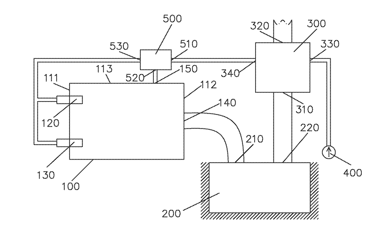
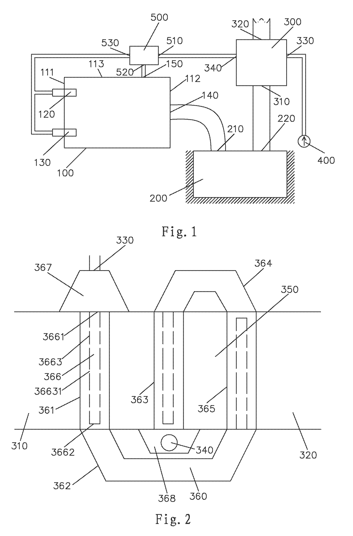
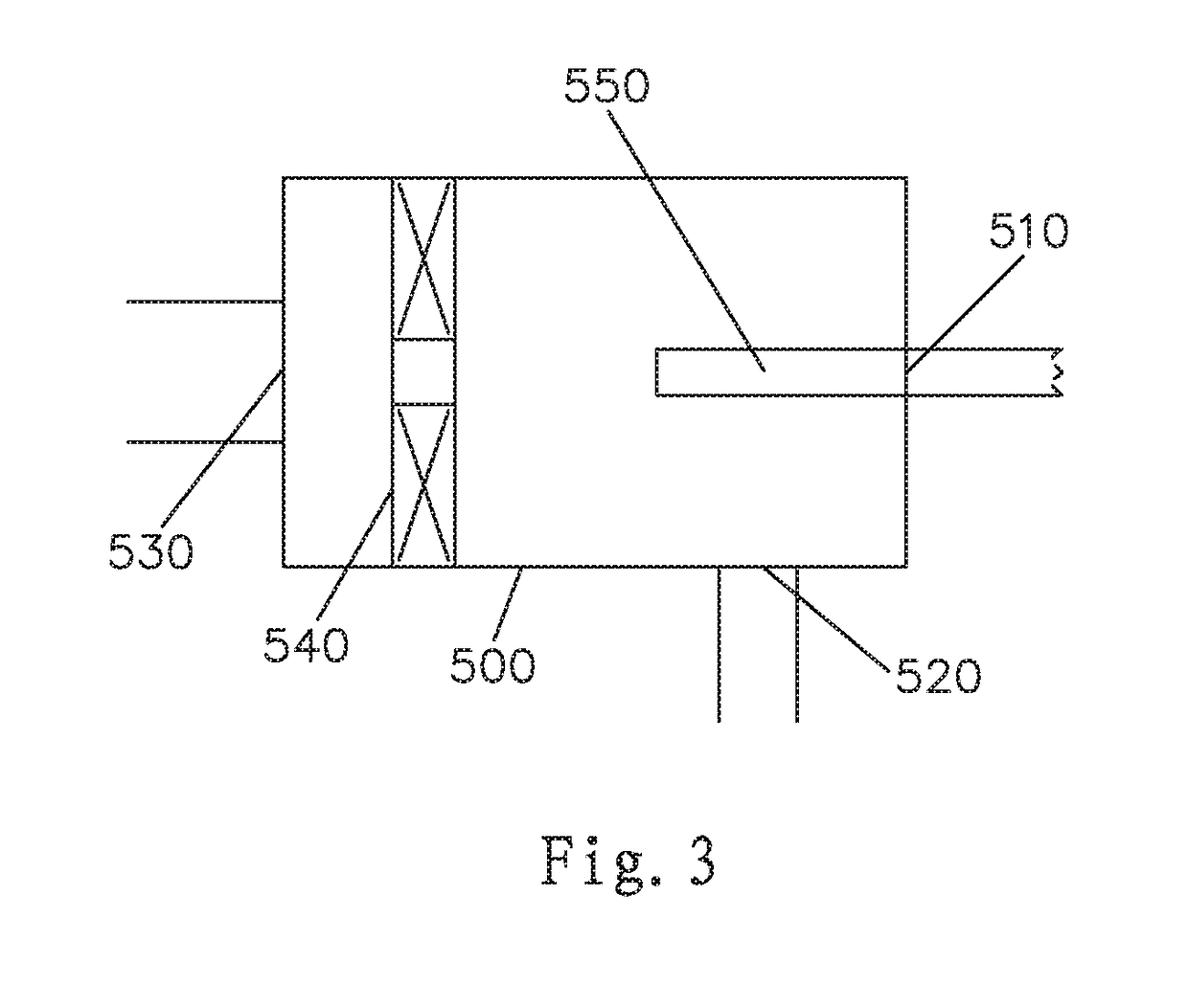
[0035]Now refer to FIGS. 1 and 2, according to one embodiment of the present invention, a continuous low oxygen and high temperature combustion aluminum melting furnace with porous injection pipe heat exchanger is comprised of a furnace body 100, a dust-removing and heat-exchanging chamber 200, a porous injection pipe heat exchanger 300, a high pressure fan 400 and a mixer 500.

[0036]The furnace body 100 comprises a first combustion nozzle 120 and a second combustion nozzle 130, which are spaced on one end wall 111 of the furnace body 100. A first high temperature flue gas outlet 140 is provided on the other end wall 112 of the furnace body 100. A second high temperature flue gas outlet 150 is provided on one side wall 113 of the furnace body 100. In operation, the first combustion nozzle 120 and the second combustion nozzle 130 are used to inject fuel and combustion-supporting gas into the furnace chamber of the furnace body 100 for combusting and releasing heat to melt aluminum.

[00...


PUM

PropertyMeasurementUnit
temperatureaaaaaaaaaa
heat-resisting aaaaaaaaaa

Abstract

A continuous aluminum melting furnace with a porous spray pipe heat exchanger, comprising a furnace body, combustion nozzles, a smoke pipeline and a heat exchanger. The heat exchanger comprises a smoke channel and heat exchange cylinders, wherein each of the heat exchange cylinders comprises a head end, a tail end, and a porous spray pipe in at least one of the cylinders. The porous spray pipe comprises a closed end and a pipe body, with several air spray holes provided on a peripheral wall of the pipe body so that cold air entering the at least one heat exchange cylinder is sprayed to an inner wall of the cylinder so as to exchange heat with high-temperature smoke which flows through an outer wall of the cylinder, thus keeping the temperature of the cylinder lower than the rated tolerant temperature of the material from which the cylinder is made.

Description

BACKGROUND OF THE INVENTIONField of the Invention[0001]The present invention relates to furnace equipment, especially to an aluminum melting furnace.Description of the Related Art[0002]In view of the increasingly urgent environmental problems and energy crisis, energy saving and emission reduction are vigorously promoted all over the world, especially for industrial furnace related fields with huge energy consumption and serious pollution. How to achieve energy-saving and emission reduction goals has become the factor that technicians in the field must consider in designing such kind of equipment.[0003]Taking aluminum melting furnaces for example, the temperature of the flue gas at the flue gas outlet may typically reaches to about 1000-1100° C. If such high temperature flue gas is exhausted to the ambient environment without further treatment, not only energy waste but also certain level of damage will be caused to the environment. Therefore, the person in the field have been conti...

Claims


Application Information

Patent Timeline
Patent Type & Authority Applications(United States)
IPC IPC(8): F27B14/14C22B21/00
CPCF27B14/143C22B21/0084F27B2014/146F27D2017/007F27D17/004F27D99/0033
Inventor LIU, XIAOZHOUZHANG, YULIU, WENXING
Owner GUANGDONG UNIV OF TECH
Learn More