Reticle disc with fiber illuminated aiming dot

a technology of illumination and focusing dot, which is applied in the field of illumination focusing dot, can solve the problems of only being used in the second focal plane, the form of illumination may not provide adequate intensity for good contrast, and the reticle can be very detailed and complex, and achieves the effect of high intensity and higher magnification power

Active Publication Date: 2018-08-09
LIGHTFORCE USA
View PDF46 Cites 10 Cited by
  • Summary
  • Abstract
  • Description
  • Claims
  • Application Information

AI Technical Summary

Benefits of technology

[0008]The present invention combines a glass substrate reticle, with more detailed reticle features for the shooter, and a fiber light guide to deliver a high intensity central aiming point, what the prior art teaches to be unworkable, by attaching an optical fiber directly to the surface of a complex etched reticle for the first focal plane. If desired, the fiber can be aligned with a major stadia line as a feature of reticle pattern on a glass plate. This construction provides a superior solution for the shooter requiring high contrast daylight visibility and long range, high wind, shooting situations. This combination provides daylight visibility of a central aiming dot, while still allowing for conventional illumination to flood light other reticle features, if desired. This can provide multiple illumination options for the user.
[0009]The present invention can be used in the first or second focal plane, but a benefit is that, in first focal plane, a detailed reticle pattern (which also can be illuminated) allows for precision aiming at longer distances and higher magnification power, while at low or no magnification an illuminated central aiming dot can be made bright enough to be seen, even in bright ambient light conditions, for close quarters engagement.

Problems solved by technology

This type of reticle can be very detailed and complex, but this form of illumination may not provide adequate intensity for good contrast during bright ambient light conditions, as the emitted light simply fans out, or floods, the reticle structure.
Systems utilizing these fiber optic light guides currently either secure the optical fiber to a metallic wire, which does not make available to the shooter other reticle features, such as extended holdover markings and “floating” wind dots, or use a self-supporting fiber post to provide the illuminated aiming dot independent of the reticle and in a different focal plane from the reticle.
It was commonly believed that this design can only be used in the second focal plane because the first focal plane would require the reticle to be much smaller to appear the correct size to the user and it is difficult to use optic fibers that small, or at least to make the center dot that small.
As described in U.S. Pat. No. 5,924,234, issued Jul. 20, 1999, and U.S. Patent Application Publication No. 2015 / 0276346, published Oct. 1, 2015, using an optical fiber with glass reticle technology for the first focal plane was believed to be unworkable without making the fiber cable visible to the observer, which could obstruct the view and could be distracting.
Wire reticles can be delicate structures that can be difficult to manufacture and less robust than a glass disc reticle.
Prior attempts recognized that it can be difficult to maintain the two reticles in separate focal planes in alignment with each other.

Method used


Image

  • Reticle disc with fiber illuminated aiming dot
  • Reticle disc with fiber illuminated aiming dot
  • Reticle disc with fiber illuminated aiming dot

Examples


first embodiment

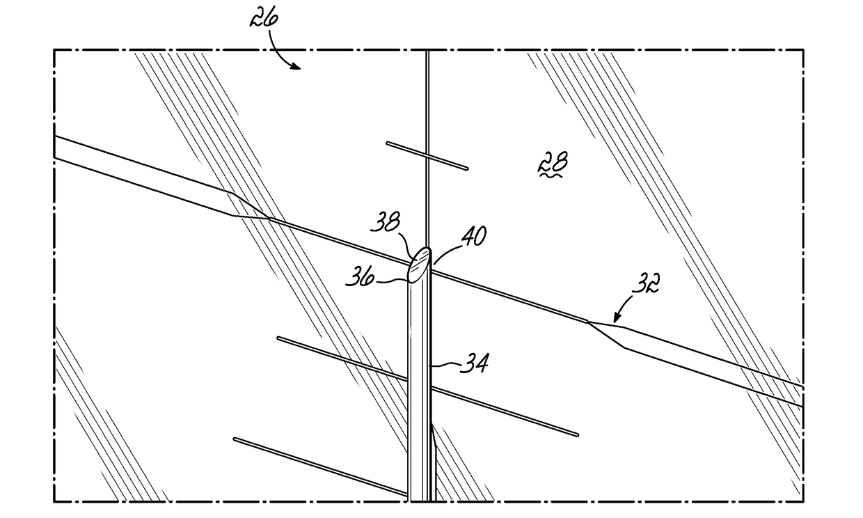
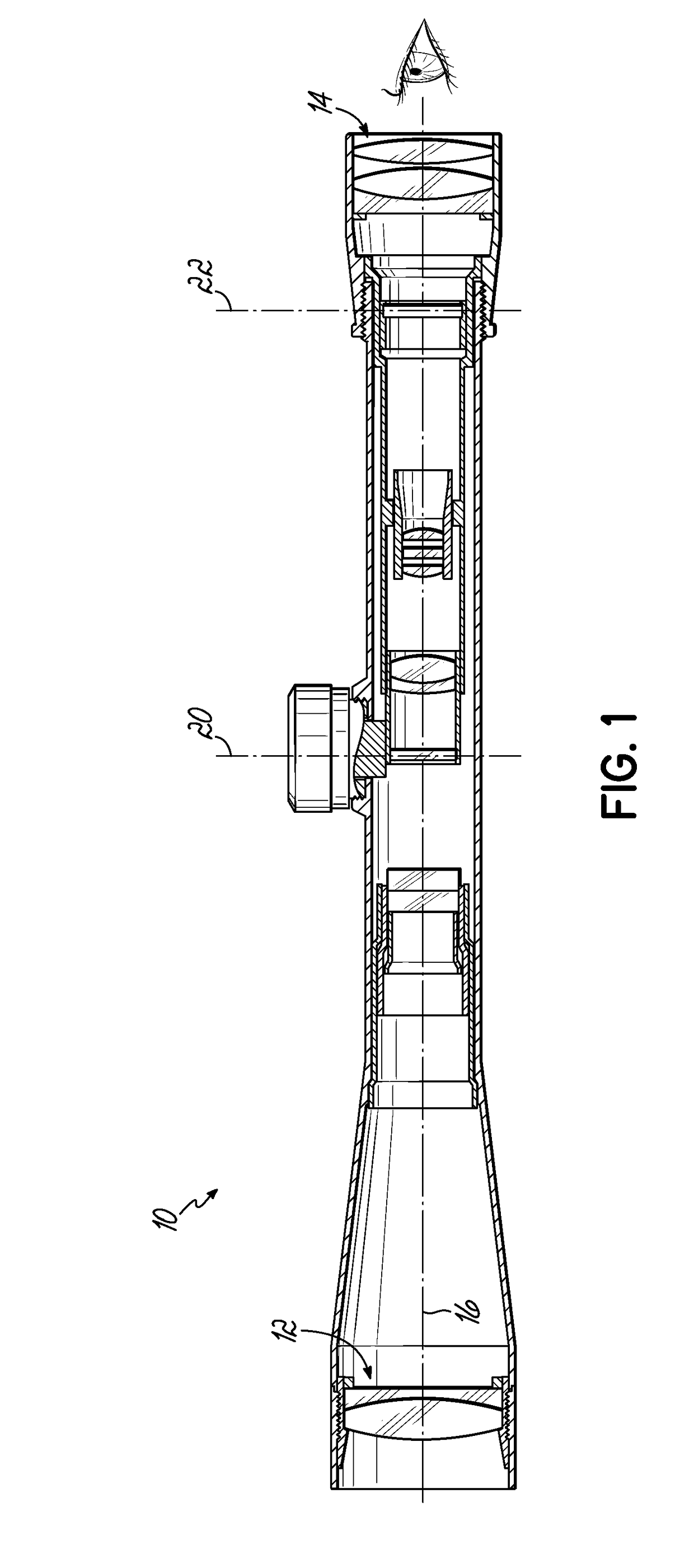
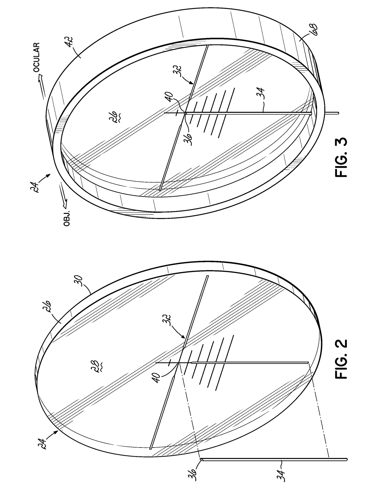
[0035]Referring now to FIGS. 2-5, in a first embodiment, a reticle disc assembly 24 is provided for an optical weapon sighting device, such as a riflescope 10. The assembly 24 includes a disc 26, typically made of high quality glass providing clarity and a high level of light transmission. The disc 26 has two substantially flat faces, an objective face 28 and an ocular face 30. When installed in a rifle scope, the objective face 28 is oriented forwardly toward the objective lens 12 and the ocular face 30 is oriented toward the ocular lens 14 and users eye (illustrated schematically in FIG. 1). A reticle pattern 32 may be applied to the disc 26, typically on the objective face 28, by etching, engraving, chromium deposit, or any other well-known means. The reticle pattern 32 may be a simple crosshair pattern, a highly detailed and complex pattern or grid providing ranging and bullet drop compensation markings, or may be any number of variants of intermediate complexity. The reticle pa...

second embodiment

[0041]Referring now to FIGS. 9-13, therein is shown a second embodiment reticle disc assembly 54, which can include a reticle disc 56 having a reticle pattern 32 on its objective face (as described above), an optical fiber 34, a spacer 58, a cover disc 60, and a frame 42. In this embodiment, the fiber 34 is illustrated extending from the top periphery of the assembly 54 along a top portion of a primary stadia line of the reticle pattern 32, although any desired orientation can be used. The fiber 34 may be secured to the reticle disc 56 as described above. As shown in FIGS. 11-13, the optical fiber 34 is “sandwiched” between the reticle disc 56 and cover disc 58. A spacer means 58 can be a unitary structure that extends substantially all the way around the periphery of the reticle disc 56 (as shown), or it may be a plurality of intermittent structures. Generally, the spacer 58 could be equal to or only very slightly greater in thickness than the thickness of the optical fiber 34. The...

third embodiment

[0042]A third embodiment reticle disc assembly 64 is shown in FIGS. 14 and 15. This embodiment includes a length of optical fiber 34, as described above, that is adhered to a wire or electroformed foil reticle 66, the combination of which is adhered to a reticle disc 68 having a reticle pattern 32 etched, engraved, or otherwise applied thereto. The optical fiber 34 can be adhered to one leg of the wire reticle 66 and the fiber 34 will be hidden along most of its length by the wire, as is known in the art. Different from known construction, however, the optical fiber 34 and wire reticle 66 can both be adhered directly to the reticle disc 68 so that all are aligned in the same focal plane 20, 22. When so assembled, the novel combination allows more complex reticle designs 32, including floating features, as well as the support of the wire reticle 66 for the optical fiber 34. By adhering them together, the reticle parts cannot become out of alignment. Additionally, also different from ...


PUM


Abstract

Provided is an illuminated dot reticle for use in a rifle scope having an optical path defined through axially spaced-apart objective and ocular lenses and method manufacturing a reticle disc assembly. A reticle disc has a first surface facing the objective lens and a second surface facing the ocular lens. A first reticle pattern, including a central aiming point, is applied to one of the reticle disc surfaces. An optical fiber has a proximal end portion and a distal end, with a light source configured to deliver light to the proximal end portion of the optical fiber. The optical fiber is secured to one of the reticle plate surfaces such that the distal end is positioned to transmit light from the light source toward the ocular lens in the optical path, providing an illuminated dot at the central aiming point.

Description

[0001]This application claims priority to U.S. Provisional Patent Application Nos. 62 / 456,905, filed Feb. 9, 2017, and 62 / 463,958, filed Feb. 27, 2017, and incorporates the same herein by reference.TECHNICAL FIELD[0002]This invention relates to providing an illuminated aiming dot, including in combination with a glass reticle disc or plate, in an optical sighting device, such as a riflescope. More particularly, it provides a reticle that can be illuminated in a traditional way, for low ambient light situations and extended range aiming, along with a separately illuminated aiming dot provided by an optical fiber attached to or integrated with the reticle plate, for high ambient light and close quarters situations.BACKGROUND[0003]A standard glass substrate reticle used in a rifle scope can be illuminated with a light emitting diode (LED) or other light source, providing the user a higher contrast between reticle design and target in low ambient light conditions. The reticle design is ...

Claims


Application Information

Patent Timeline
Patent Type & Authority Applications(United States)
IPC IPC(8): F41G1/34F41G1/38
CPCF41G1/345F41G1/38
Inventor BELLAH, BRIAN J.MINOR, GRANT M. W.
Owner LIGHTFORCE USA
Why Eureka
Try Eureka