Camera-Biometric motion sensor and method of synchronization

a biometric and motion sensor technology, applied in the field of camerabiometric motion sensor and method of synchronization, can solve the problems of inability to synchronize the time base of smartphones and the motion sensor for 400 ms uncertainty or delay, and achieve the effect of saving the time valu

Active Publication Date: 2018-08-09
JAWKU L L C A DELAWARE CO
View PDF0 Cites 5 Cited by
  • Summary
  • Abstract
  • Description
  • Claims
  • Application Information

AI Technical Summary

Benefits of technology

[0006]Upon receiving the triggering signal, the smartphone transmits a RF (Radio Frequency) stop request to the motion sensor to cause, the sensor to capture and save the time value on receipt of the RF request. The sensor sends this captured start time T′(Start) which is really the actual start time T(Start) plus a time error T(Error) to the smartphone. The smartphone runs a previously loaded one-time crystal calibration routine to remove the time error T(Error). The difference in the start time T(Start) and the stop time T(Stop) recorded by the photo stamp time app equals the true run time. The previously mentioned security enhancements to the operating systems of the smartphones cause the unacceptable 400 ms uncertainty or delay in the motion sensor and smartphone synchronization of time bases caused by relative time base drift errors. The present invention corrects for these drift errors by having the smartphone upon receiving the start time T′(Start) run the one-time crystal calibration routine upon the smartphone receiving the captured start event time. Due to this calibration, T(error) is accurately calculated and is removed from the captured run time. This delay in synchronization can be determined at the factory manufacturing the motion sensor sparing the user from having to re-sync. As above disclosed the delay is subtracted from the measured sprint time. By performing a large number of trials at the factory, the average delay and the SD (Standard Deviation) of the delay can be characterized. The average value of the characterized delay determined at the factory is subtracted from the measured sprint time, leaving only the residual SD as the error which need be done only once at the factory.

Problems solved by technology

The previously mentioned security enhancements to the operating systems of the smartphones cause the unacceptable 400 ms uncertainty or delay in the motion sensor and smartphone synchronization of time bases caused by relative time base drift errors.

Method used


Image

  • Camera-Biometric motion sensor and method of synchronization
  • Camera-Biometric motion sensor and method of synchronization
  • Camera-Biometric motion sensor and method of synchronization

Examples


Embodiment Construction

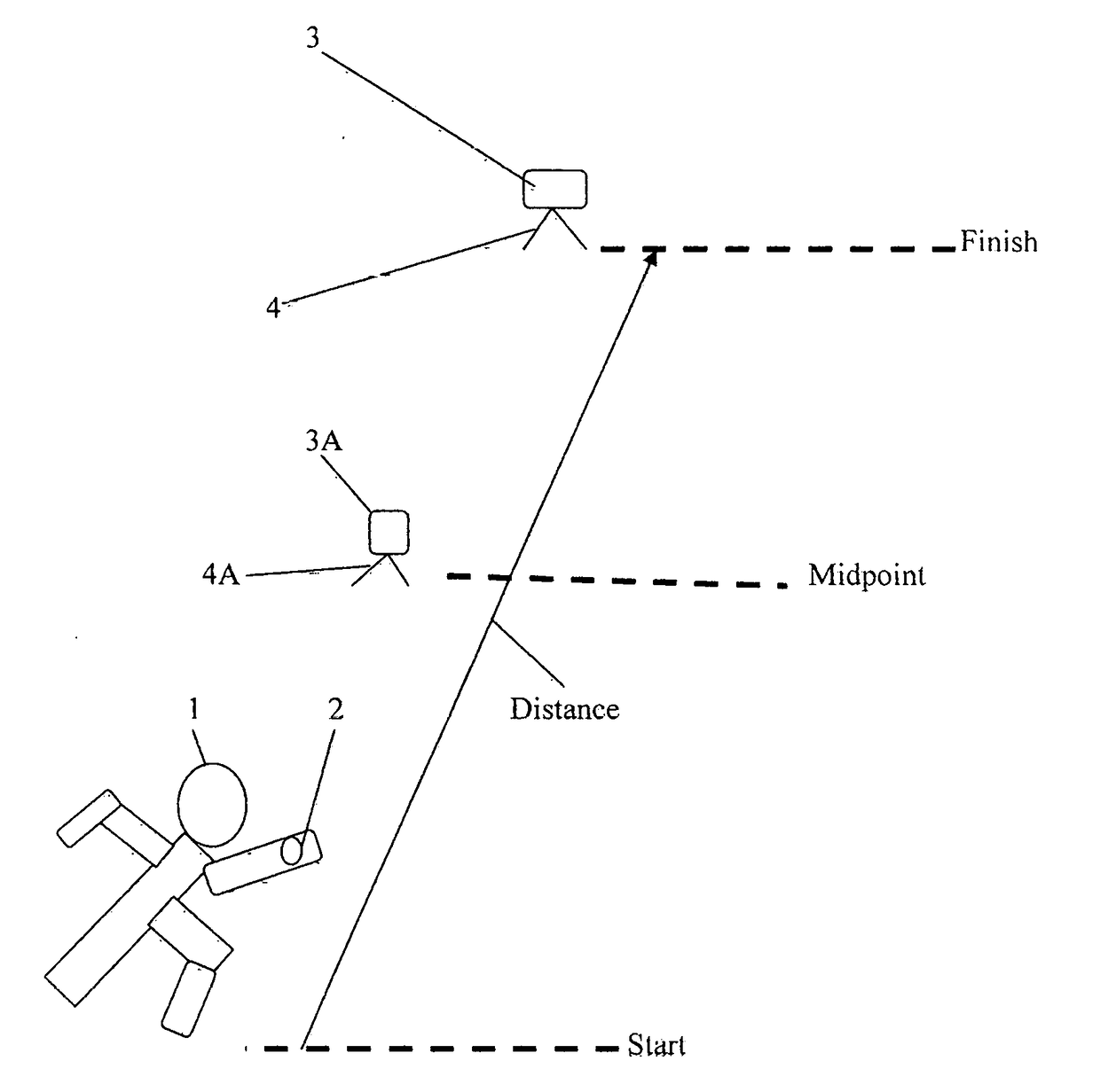
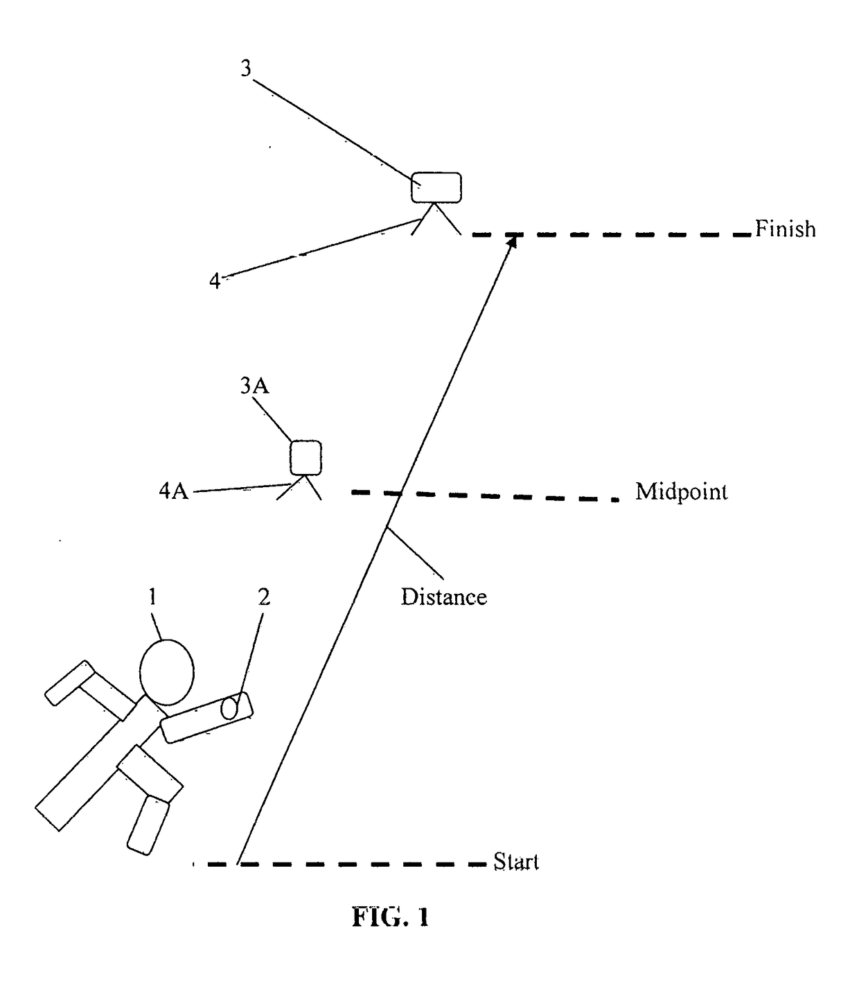
[0012]Referring to FIG. 1, an athlete 1, wearing a motion sensor 2 on a wrist is starting to traverse a premeasured or predetermined distance, such as a 40 yard sprint. The athlete has previously prepositioned a smart device, such as a smartphone 3, on a tripod 4. The motion sensor 2 is a 6-DOF mems more fully explained in the previously referenced U.S. patent application Ser. No. 14 / 121,226. In the art, the term “6-DOF” refers to six degrees of freedom represented by the x, y, and z axis of movements. The term “mems” refers to miniature electrical mechanical systems. The motion parameters are sensed using an acceleration sensor and gyroscope sensor for each axis which acceleration sensors and gyroscope sensors are integrated in the motion sensor.

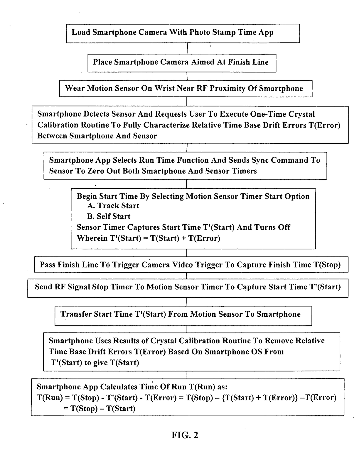
[0013]Referring to FIG. 2, a photo stamp time app is loaded into the smartphone to capture the finish time when the athlete crosses the finish line. The smartphone 3 has a camera which is aligned with the finish line of the predetermined di...


PUM


Abstract

An athlete (1) measures sprint time by locating a smartphone (3) having a camera and crystal osillator clock which is first activated at the finish line. The sprint end time is recorded by a photo stamp time app activated by a video trigger causing the smartphone (3) to send a RF stop event signal to the athlete's wrist mounted motion sensor (2). Before this a sensor timer or clock is started via the sprinter's start event. The sprinter's start activates the sensor's clock and saves the captured start time including time drift error. Upon the phone app selecting the run time function, a sync command sent to the sensor (2) by the app zeros out the phone and sensor timers. A one-time crystal calibration routine correcting for drift errors caused by the smartphone's operating system is activated which provides the sprint with a corrected start time.

Description

CROSS-REFERENCE TO RELATED APPLICATIONS / INCORPORATED BY REFERENCE[0001]This application makes reference to, claims priority to, and claims the benefit of U.S. Provisional Application Ser. No. 62 / 499,725 filed Feb. 6, 2017 entitled “Camera-Biometric Motion Sensor and Method of Synchronization”. This application makes reference to and incorporates in its entirety by reference U.S. patent application Ser. No. 14 / 121,226 filed Aug. 14, 2014, now published as US2015-0287338A1 and entitled “BIOMETRIC DATA GATHERING” ad now U.S. Pat. No. 9,704,412B1. The present application incorporates by reference in their entirety Provisional Applications 62 / 178,034, filed Mar. 31, 2015, entitled “Clap-Sync Timers and Method” and 62 / 282,571, filed Aug. 5, 2015, and entitled “Camera-Biometric Motion Timer and Method”. The present application incorporates by reference International Application No. PCT / US2016 / 013145 published as WO 2016 / 160091A1 which is a combination of the above Provisional Applications ...

Claims


Application Information

Patent Timeline
Patent Type & Authority Applications(United States)
IPC IPC(8): G07C1/24A61B5/00H04W4/02
CPCG07C1/24A61B5/6801H04W4/023A61B5/0022A61B5/0024A61B5/1128A61B5/681A61B5/6898A61B5/7405A61B5/7455A61B5/746A61B2560/0223A61B2562/0219G03B15/00G03B17/38
Inventor KOLEN, PAUL T.WELLS, JOHN ANDREW
Owner JAWKU L L C A DELAWARE CO
Why Eureka
Try Eureka