Engine control device

a control device and engine technology, applied in the direction of electric control, ignition automatic control, engine starters, etc., can solve the problems of prolonging the time of the spark discharge caused by the ignition plug, aggravating emissions, and reducing the service life of the engine, so as to reduce the risk of ignition coil premature degradation, prolong the service life, and reduce the effect of fuel consumption

Inactive Publication Date: 2018-08-16
TOYOTA JIDOSHA KK
View PDF2 Cites 6 Cited by
  • Summary
  • Abstract
  • Description
  • Claims
  • Application Information

AI Technical Summary

Benefits of technology

[0018]That is, even when the crankshaft is reversely operated after the start of the energization to the ignition coil resulting from the spark discharge caused by the ignition plug as described above and the energization cutoff timing is not reached, there is no case where the energization time becomes extremely long as described above. Therefore, the wasteful power consumption can be further suppressed, and the premature degradation of the ignition coil can be further restrained.
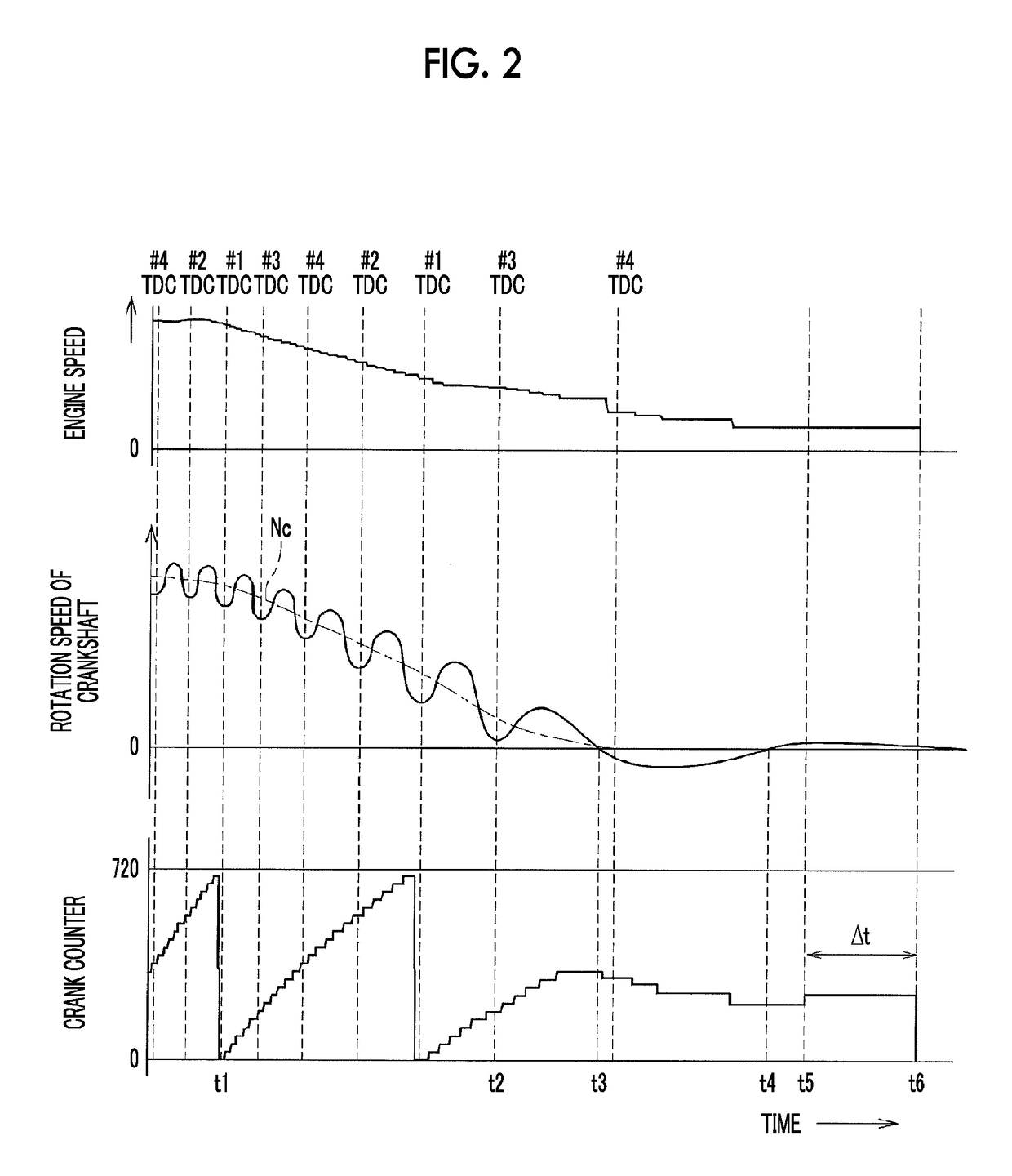
[0019]According to the control device of the aspect of the present disclosure as described above, when the operation of the engine is stopped, the spark discharge caused by the ignition plug is continued for a while even after the supply of the fuel is stopped. Accordingly, the unburned fuel within the cylinder can be combusted. In the first aspect of the present disclosure, when the rotation speed of the crankshaft decreases gradually and becomes equal to or lower than the threshold value, the spark discharge caused by the ignition plug is stopped. Accordingly, the wasteful power consumption can be further suppressed, and a situation in which the energization time to the ignition coil becomes extremely long can be further suppressed.
[0020]In the second aspect of the present disclosure, the energization start timing to the ignition coil is retarded as the rotation speed of the crankshaft decreases gradually as described above. Accordingly, the wasteful power consumption can be further suppressed, and a situation in which the energization time to the ignition coil becomes extremely long can also be further suppressed. In the third aspect of the present disclosure, the energization is cut off when the crankshaft is reversely operated. Accordingly, the energization time can be further restrained from becoming extremely long.
[0021]Therefore, by virtue of the first to third aspects of the present disclosure, the wasteful power consumption can be further suppressed without causing the aggravation of emissions when the engine is stopped, the premature degradation of the ignition coil resulting from the energization time becoming extremely long can be further restrained.

Problems solved by technology

However, in a case where the spark discharge caused by the ignition plug is continued for a while after a fuel cut as described above, the duration time of the spark discharge caused by the ignition plug becomes a problem.
That is, when the time for which the spark discharge caused by the ignition plug is continued is significantly shorter than usual, the unburned fuel within the cylinder cannot be sufficiently combusted and may be released into the ambient air.
Thus, there is a possibility that aggravation of emissions is caused.
On the other hand, continuing an unneeded spark discharge caused by the ignition plug until after unburned fuel is substantially exhausted leads to an increase in wasteful power consumption.
Energization time may become extremely long due to the reverse operation of a crankshaft immediately before the stop of the engine.
As a result, degradation of the ignition coil may be accelerated, and there is also a possibility that the service life of the ignition coil is shortened.
Thus, the crankshaft is not able to exceed a top dead center in a compression stroke of one of the cylinders.

Method used


Image

  • Engine control device
  • Engine control device
  • Engine control device

Examples


modification example 1

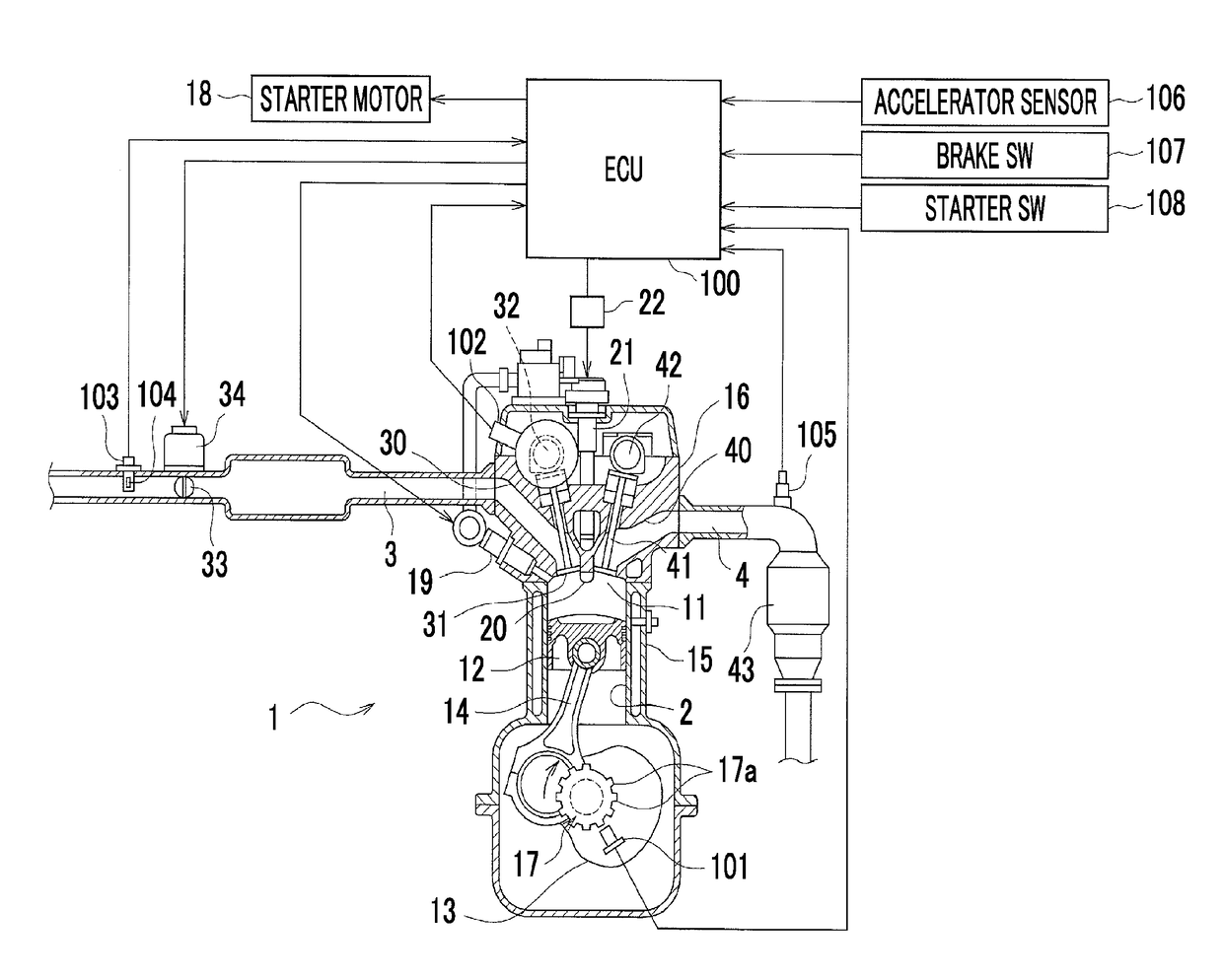
[0087]Modification Example 1 in which a timing for starting the energization (energization start timing) to the ignition coil 21 is retarded in accordance with a decrease in the crank rotation speed Nc at an automatic stop of the engine 1 will be described with reference to FIGS. 6 and 7. Also in Modification Example 1, the configuration of the control system of the engine 1, the procedure of the stop and start control, and the like are the same as those of the above-described embodiment, and different portions will be described below.

[0088]A routine of the automatic stop processing related to Modification Example 1 is illustrated in FIG. 6, and first, the same processing as Steps ST201 to ST203 of the flow of FIG. 4 is performed in Steps ST301 to ST303 after a start. When a negative determination (NO) that the crank rotation speed Nc is higher than the threshold value Nc1 is made in Step ST303, the process proceeds to Step ST304, the spark discharge caused by the ignition plug that...

modification example 2

[0095]Modification Example 2 in which the energization to the ignition coil 21 is cut off in accordance with the reverse operation of the crankshaft 13 without changing the spark discharge caused by the ignition plug according to a decrease in the crank rotation speed Nc like the above embodiment and Modification Example 1 will be described with reference to FIGS. 8 and 9. Also in Modification Example 2, the configuration of the control system of the engine 1, the procedure of the stop and start control, and the like are the same as those of the above embodiment, and different portions will be described below.

[0096]The routine of the automatic stop processing related to the modification example 2 is illustrated in FIG. 8. First, in Step ST401 after start, a fuel cut is performed similar to Step ST201 of the flow of FIG. 4, and in Step ST402, processing of the spark discharge caused by the ignition plug is performed similar to Step ST204. Accordingly, when the rotation speed of the c...


PUM


Abstract

An engine control device includes an electronic control unit. The electronic control unit is configured to perform a spark discharge with an ignition plug for each cylinder by cutting off energization after elapse of a predetermined period from start of energization to an ignition coil for each cylinder of the engine, to stop the spark discharge caused by the ignition plug for each cylinder after supply of fuel to the engine is stopped when operation of the engine is stopped, and to control an ignition plug so as to stop the spark discharge caused by the ignition plug from a cylinder after a rotation speed of a crankshaft decreases gradually and the rotation speed of the crankshaft reaches a preset threshold value or less, after the stop of the supply of fuel to the engine.

Description

INCORPORATION BY REFERENCE[0001]The disclosure of Japanese Patent Application No. 2017-026602 filed on Feb. 16, 2017 including the specification, drawings and abstract is incorporated herein by reference in its entirety.BACKGROUND1. Technical Field[0002]The present disclosure relates to a control device that stops the supply of fuel to an engine and ignition of the fuel to stop the operation of the engine, and particularly, to a spark discharge caused by an ignition plug for each cylinder.2. Description of Related Art[0003]Generally, a system (stop and start system), which automatically stops an engine of a vehicle during idling or the like and then automatically restarts the engine, is well-known in the related art. When the engine is stopped in the system as described above, normally, a throttle valve is closed, supply of fuel by an injector is stopped (fuel cut), and then, a spark discharge caused by an ignition plug is continued for a while, and the spark discharge caused by the...

Claims


Application Information

Patent Timeline
Patent Type & Authority Applications(United States)
IPC IPC(8): F02P5/15F02D41/04
CPCF02P5/1502F02D41/042F02D2200/101F02D37/02F02D41/009F02D2250/06F02N11/0814F02N2250/04F02P3/0556F02P5/045F02P5/1504F02P11/025Y02T10/40
Inventor HAYASHIMA, NAOKIYOSHIHARA, MASATOMOMURAKAMI, KOJI
Owner TOYOTA JIDOSHA KK
Why Eureka
Try Eureka