Wind turbine blade with anchoring sites

Active Publication Date: 2018-08-16
LM WP PATENT HLDG
View PDF17 Cites 8 Cited by
  • Summary
  • Abstract
  • Description
  • Claims
  • Application Information

AI Technical Summary

Benefits of technology

The present invention provides a wind turbine blade with attachment sites for surface mounted devices. These attachment sites are made of thermoplastic material, which makes it easier and safer to attach devices to the blade. The thermoplastic material may also improve the bonding with the device and enhance the integration with the blade's shell body. Having dedicated attachment sites integrated in the blade reduces the need for control when attaching new devices or repairing existing ones.

Problems solved by technology

One problem in this regard is that such add-ons may fall of the blade during operation or may loosen over time which may cause a drop in blade performance with regard to energy generation, operational noise and safety.
This in turn causes costly down time and repairs.

Method used


Image

  • Wind turbine blade with anchoring sites
  • Wind turbine blade with anchoring sites
  • Wind turbine blade with anchoring sites

Examples


Embodiment Construction

[0087]The invention is explained in detail below with reference to an embodiment shown in the drawings, in which

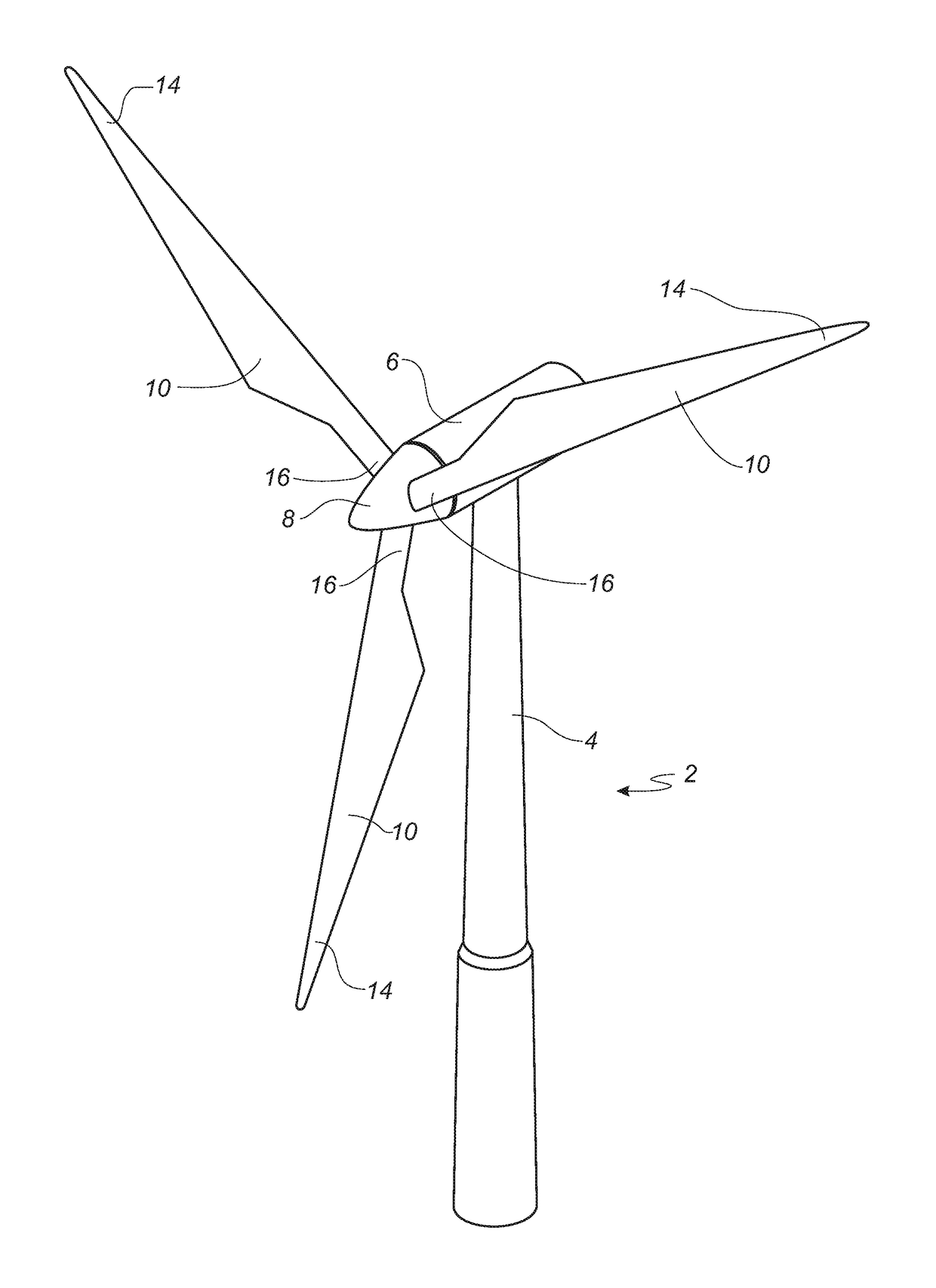
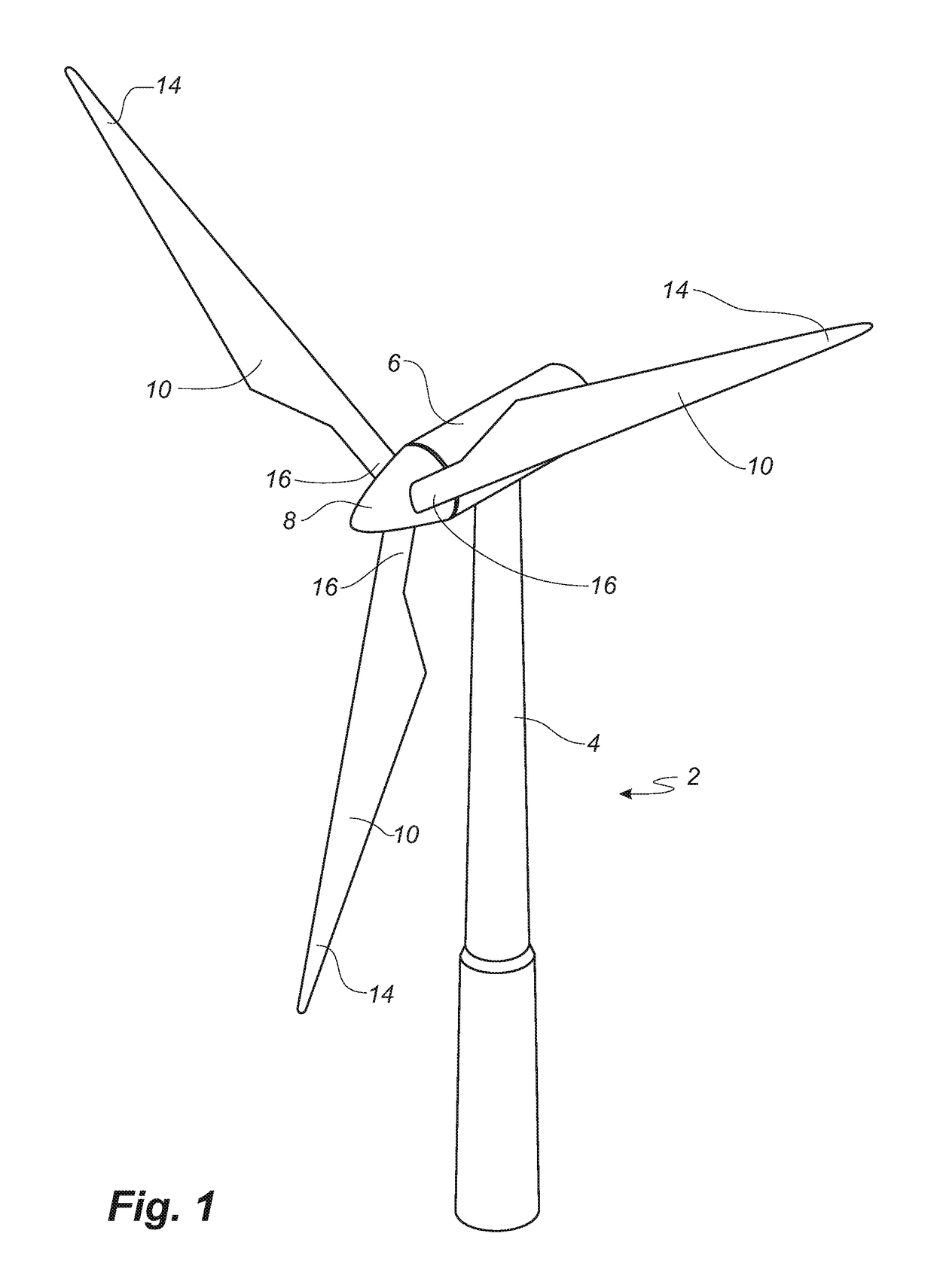
[0088]FIG. 1 shows a wind turbine,

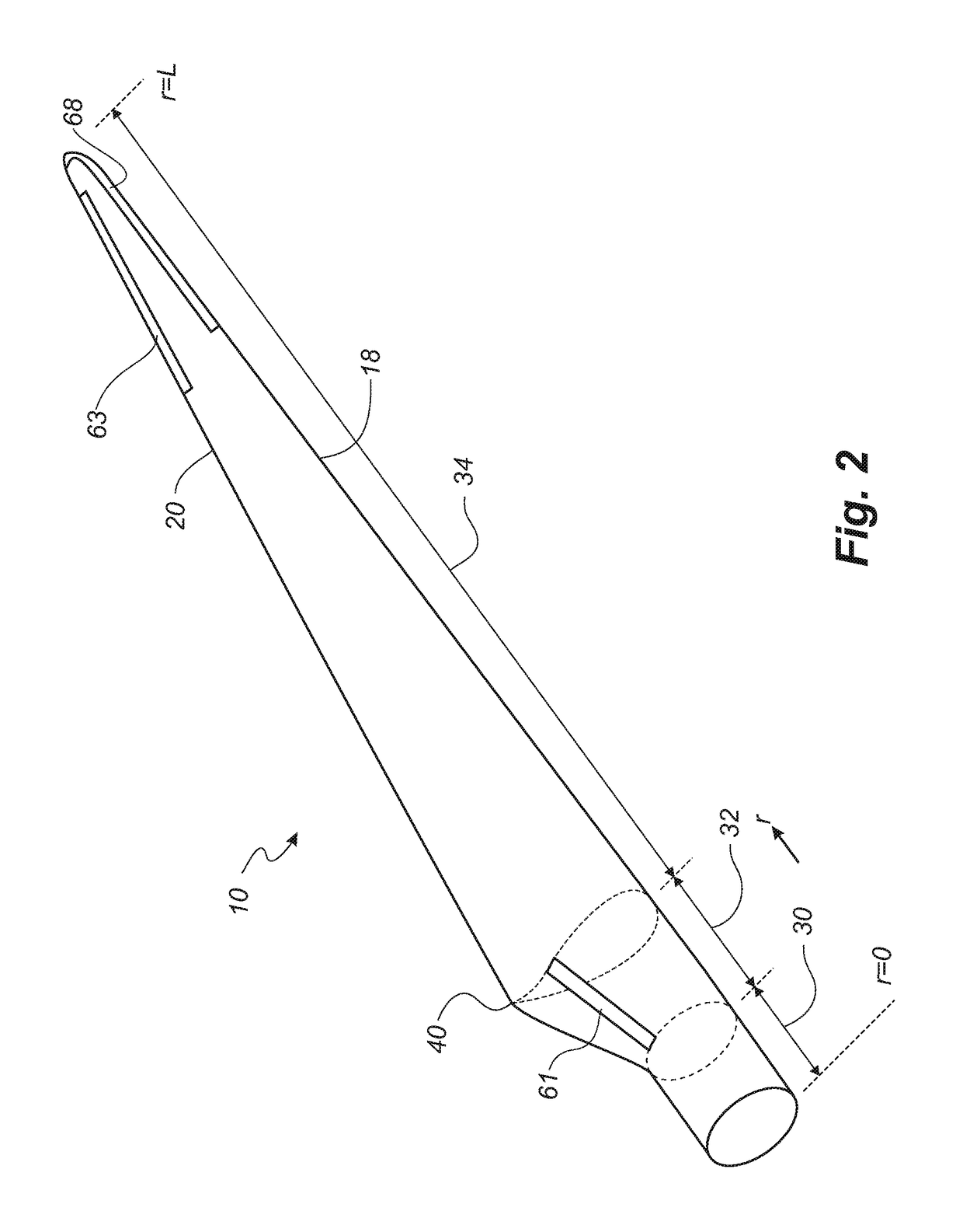
[0089]FIG. 2 shows a schematic view of a wind turbine blade according to the invention,

[0090]FIG. 3 shows a schematic view of an airfoil profile,

[0091]FIG. 4 shows a schematic view of the wind turbine blade according to the invention, seen from above and from the side,

[0092]FIG. 5 shows a schematic view of an airfoil profile having an erosion shield comprised of two layers of thermoplastic materials at the leading edge,

[0093]FIG. 6 shows a schematic view of an airfoil profile of two shell body parts having an integrated first thermoplastic material in a recess at the leading edge,

[0094]FIG. 7 shows a schematic view of an erosion shield comprised of 2 layers of thermoplastic materials joined together.

[0095]FIG. 8 shows a schematic view of pre-formed parts of a first—and a second thermoplastic material, respectively.

[0096]FIG. 9 shows a sche...


PUM

PropertyMeasurementUnit
Thicknessaaaaaaaaaa
Thicknessaaaaaaaaaa
Thicknessaaaaaaaaaa

Abstract

The invention relates to a wind turbine blade having integrated thermoplastic anchoring sites for attachment of surface mounted devices, a method for producing such blade and a wind turbine equipped with such blade.

Description

FIELD OF THE INVENTION[0001]The present invention relates to a wind turbine blade, a wind turbine having such blade and a method of manufacturing such blade.BACKGROUND OF THE INVENTION[0002]Modern wind turbine blades may require surface mounted devices, also known as add-ons, attached to the aerodynamic shell of the blade.[0003]Such add-ons are typically adhered to the aerodynamic shell of the blade at various positions by using different types of adhesives or double sided tape.[0004]WO 13 060493 describes vortex generators fixed to a wind turbine blade by using adhesives.[0005]It is thus known to adhesively attach various components such as spoilers and serrations to wind turbine blades.[0006]One problem in this regard is that such add-ons may fall of the blade during operation or may loosen over time which may cause a drop in blade performance with regard to energy generation, operational noise and safety.[0007]This in turn causes costly down time and repairs.[0008]It is an object...

Claims


Application Information

Patent Timeline
IPC IPC(8): F03D1/06B29C65/08B29C65/10B29C65/16B29C65/50B29C65/00B29D99/00
CPCF03D1/0675B29C65/08B29C65/10B29C65/16B29C65/5057B29C66/721B29D99/0025B29L2031/085F05B2240/2211F05B2250/70F05B2280/4007F05B2280/6003B29C65/0681B29C65/1635B29C65/1677B29C65/18B29C65/48B29C65/4815B29C65/4895B29C66/1142B29C66/1162B29C66/301B29C66/532B29C66/54B29C66/71B29C66/73941B29C65/02F05B2240/3042F05B2240/305Y02E10/72Y02P70/50B29K2067/00
Inventor DRACHMANN HAAG, MICHAEL
Owner LM WP PATENT HLDG
Why Eureka
Try Eureka