
Method for controlling electric power conversion system and control arrangement for electric power conversion system

Active Publication Date: 2018-08-16
MARICI HLDG THE NETHERLANDS BV
View PDF4 Cites 5 Cited by
  • Summary
  • Abstract
  • Description
  • Claims
  • Application Information

AI Technical Summary

Benefits of technology

The solution in this patent allows for a better optimization of an electric power conversion system based on the current conditions. This means that the system can work at its best level of efficiency based on the specific circumstances it is facing.

Problems solved by technology

A problem related to such a system is that the system as a whole may not be sufficiently optimized and comprises a group of merely sub-optimized electric power converters.
Moreover, such a system may not able to properly or adequately adapt to new situations or circumstances affecting the system.

Method used

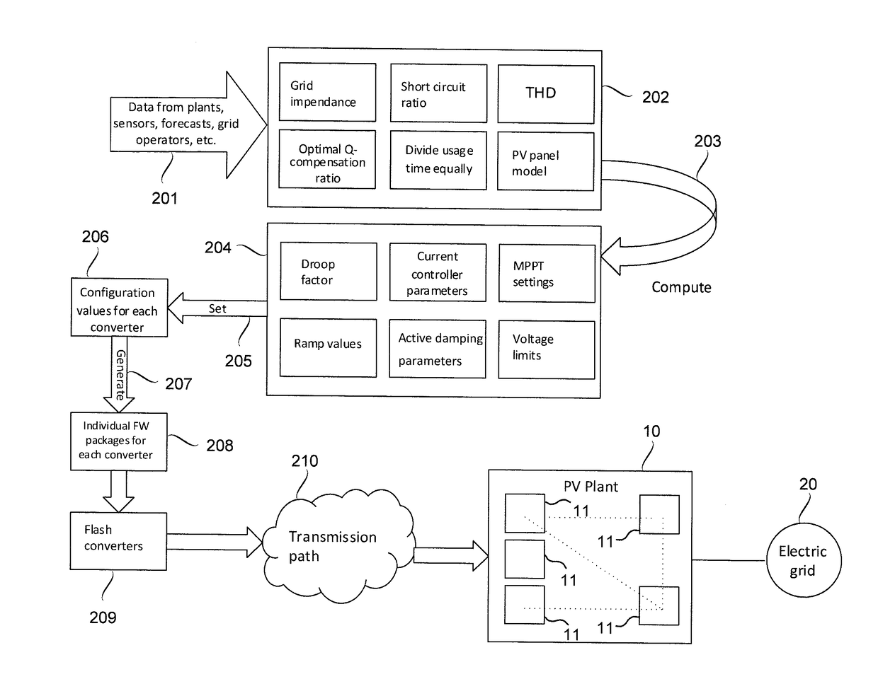
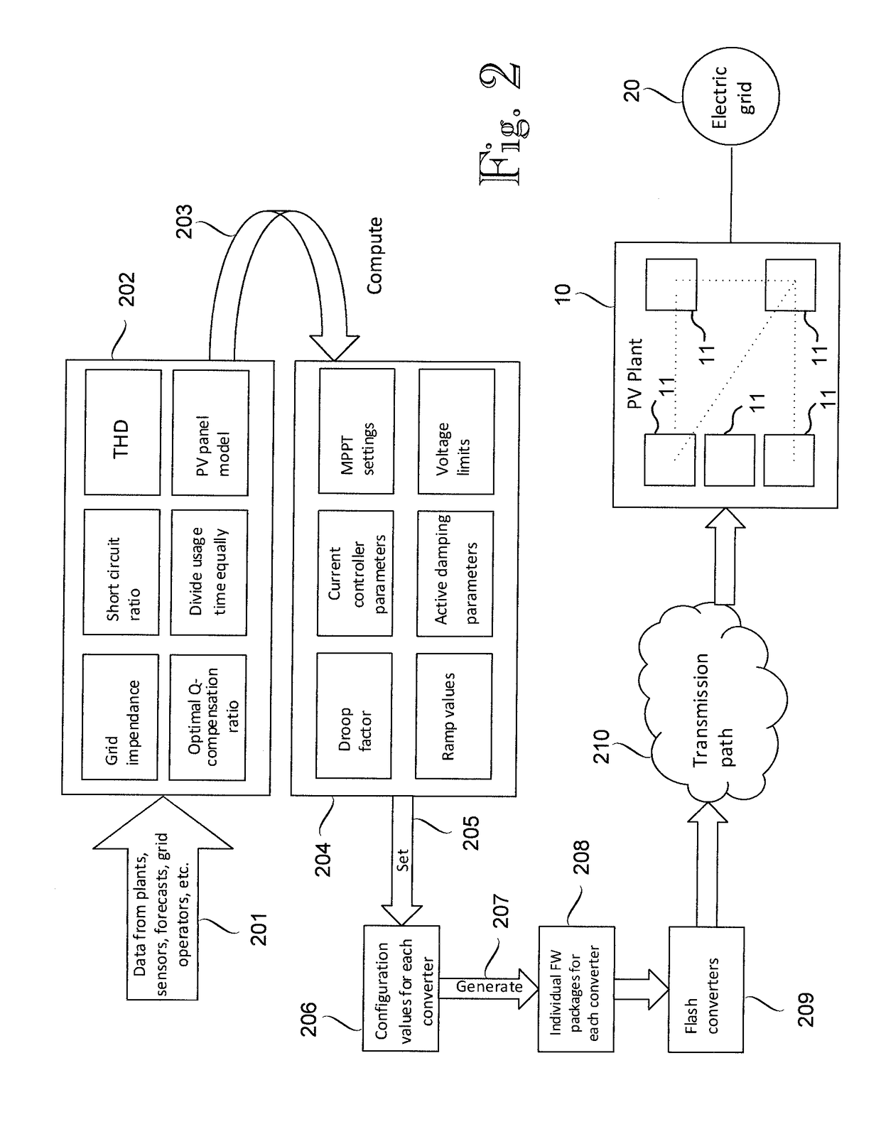

Image

  • Method for controlling electric power conversion system and control arrangement for electric power conversion system
  • Method for controlling electric power conversion system and control arrangement for electric power conversion system
  • Method for controlling electric power conversion system and control arrangement for electric power conversion system

Examples


Embodiment Construction

[0016]The application of the various embodiments described herein is not limited to any specific system, but they can be used in connection with various electric power conversion systems comprising electric power converters. Moreover, the use of the various embodiments described herein is not limited to systems employing any specific fundamental frequency or any specific voltage level, for example.

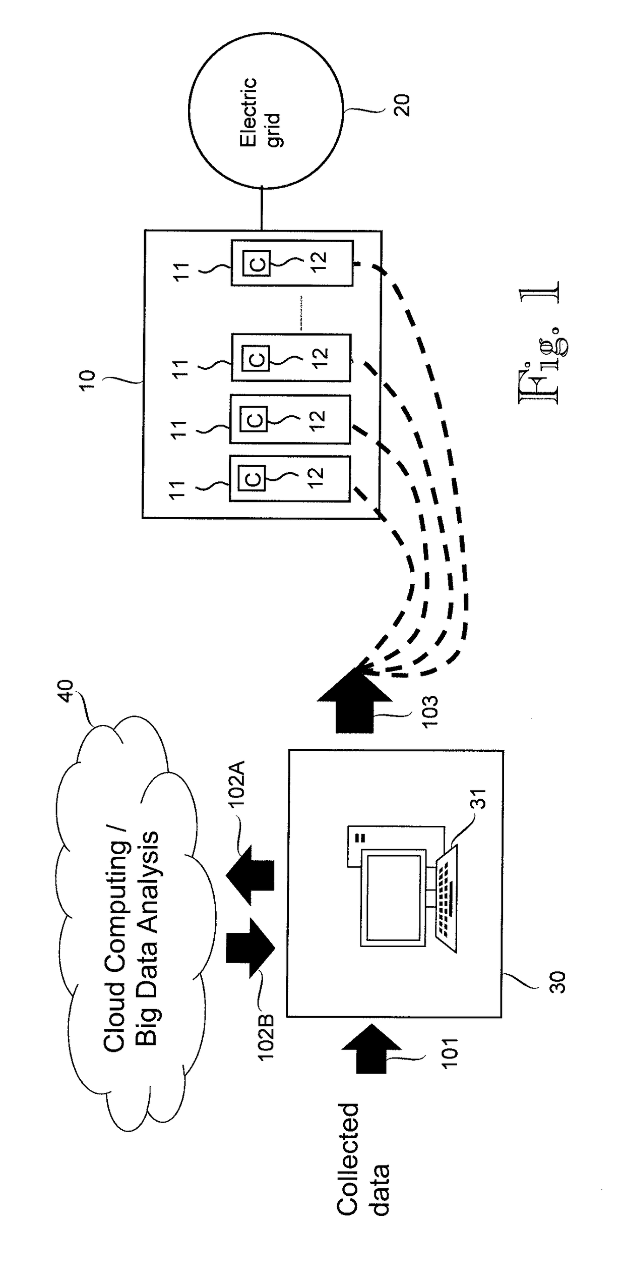
[0017]FIG. 1 illustrates a simplified example of an arrangement for controlling an electric power conversion system 10 according to an embodiment. The figure shows only components necessary for understanding the invention. The electric power conversion system 10 may be any kind of electric power conversion system comprising a plurality of electric power converters 11. As an example, the power conversion system 10 could be a photovoltaic power plant or another kind of power plant supplying an electric grid 20, such as an AC network, or merely a power conversion arrangement for such a photov...


PUM


Abstract

A method and a control arrangement for an electric power conversion system including a plurality of electric power converters, the control arrangement configured to collect data related to the electric power conversion system, determine an optimal configuration for each one of the electric power converters of the electric power conversion system on the basis of collected data through a simulation of the electric power conversion system generate, for each one of the electric power converters, a source code for a firmware of the electric power converter on the basis of the determined optimal configuration for the electric power converter in question, and re-program each one of the electric power converters with the respective source code generated for the electric power converter in question.

Description

FIELD OF THE INVENTION[0001]The present invention relates to a method for controlling an electric power conversion system and to a control arrangement for an electric power conversion system.BACKGROUND OF THE INVENTION[0002]Electric power converters are devices that enable the conversion of electric energy between AC (alternating current) and DC (direct current) and / or from one voltage level to another and / or from one frequency to another, for example. Examples of such electric power converters include a rectifier, an inverter and a frequency converter, for example.[0003]As an example, an inverter is an electrical device enabling conversion of DC power from a DC power source to AC power. The term ‘inverter’ generally refers to an electronic device or circuitry that is able to convert direct current to alternating current. An example of the inverter is a semiconductor bridge implemented by means of controllable semiconductor switches, such as IGBTs (Insulated-gate Bi-polar Transistor...

Claims


Application Information

Patent Timeline
IPC IPC(8): H02J3/38G05B19/042
CPCH02J3/385G05B19/0426H02J2003/007G05B2219/23456G05B2219/23146H02M1/00H02M1/0003H02M3/00H02M5/00H02M7/00H02M11/00Y04S10/123H02J2203/20H02J2300/26H02J2300/24H02J3/381Y02E10/56Y02E40/70H02M1/0012H02J13/00002Y02E60/00Y04S10/30H02J3/38
Inventor KANGAS, JANIRIIPINEN, TOMI
Owner MARICI HLDG THE NETHERLANDS BV
Learn More