Imaging system for generating vibration region caused by ultrasound wave thereby to obtain optically-sectioned images

a technology of ultrasound wave and optically-sectioned images, which is applied in the direction of ultrasonic/sonic/infrasonic image/data processing, instruments, applications, etc., can solve the problems of inability to accurately reconstruct the elasticity distribution of the tissue, poor imaging resolution, etc., and achieve accurate detection, accurate adjustment of the effective frame rate of the imaging system, and reduction of the error in the stiffness estimation of the high elasticity object

Active Publication Date: 2018-08-23
NAT TAIWAN UNIV
View PDF3 Cites 2 Cited by
  • Summary
  • Abstract
  • Description
  • Claims
  • Application Information

AI Technical Summary

Benefits of technology

[0009]In accordance with an embodiment of the imaging system for generating vibration region caused by ultrasound wave to obtain a plurality of optically-sectioned images of the present invention, the imaging system for generating vibration region caused by ultrasound wave to obtain a plurality of optically-sectioned images further comprises a beam expansion device. The beam expansion device is located on the beam propagation path between the laser generating device and the translational stage, for expanding the illumination region of the laser beam. The beam expansion device is a combination of a concave lens and a convex lens. In addition, the optical focusing device comprises an aperture stop and at least two lenses. The aperture on the aperture stop partially allows the light beam to pass. The at least two lenses are located on the either side of the aperture stop along the beam propagation path, for adjusting the focusing position.
[0010]In accordance with an embodiment of the imaging system for generating vibration region caused by ultrasound wave to obtain a plurality of optically-sectioned images of the present invention, the imaging system for generating vibration region caused by ultrasound wave to obtain a plurality of optically-sectioned images further comprises a control device, which is electrically connected to the ultrasound device and the optical imaging device, for controlling the driving sequence for ultrasound device to transmit the ultrasound wave and optical imaging device to record optical image of the object, so as to adjust the effective frame rate of the imaging system. If the effective frame rate is high, the propagation speed of the shear wave can be accurately detected such that the error in the stiffness estimation of the high elasticity object can be reduced.
[0011]By using the imaging system for generating vibration region caused by ultrasound wave to obtain a plurality of optically-sectioned images provided in the present invention, which uses the ultrasound wave to generate the vibration region on the object to be detected, moves the object along a plurality of scanning imaging positions to generate images corresponding to the scanning imaging positions, and processes these images to generate the elasticity image, thereby, the elasticity distribution of the object can be reconstructed effectively by using the sectioned images. The ability to detect stiff nodule accurately is helpful and convenient for both research and practical applications.

Problems solved by technology

The common problem of the conventional elasticity imaging techniques is that the imaging resolution is still relatively poor, and elasticity distribution of the tissue may not be accurately reconstructed.

Method used


Image

  • Imaging system for generating vibration region caused by ultrasound wave thereby to obtain optically-sectioned images
  • Imaging system for generating vibration region caused by ultrasound wave thereby to obtain optically-sectioned images
  • Imaging system for generating vibration region caused by ultrasound wave thereby to obtain optically-sectioned images

Examples


Embodiment Construction

[0017]There are various embodiments of the imaging system for generating vibration region caused by ultrasound wave to obtain a plurality of optically-sectioned images provided in accordance with the present invention, which are not repeated hereby. Only one preferred embodiment is mentioned in the following paragraph as an example.

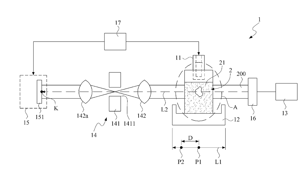
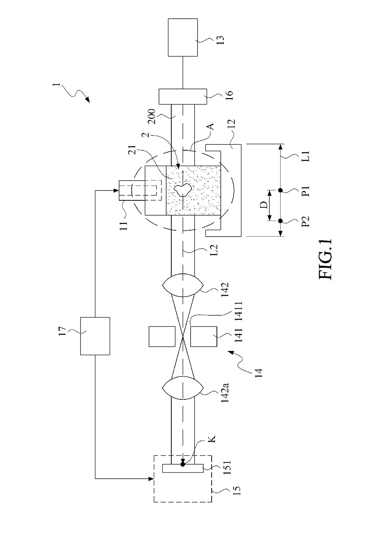
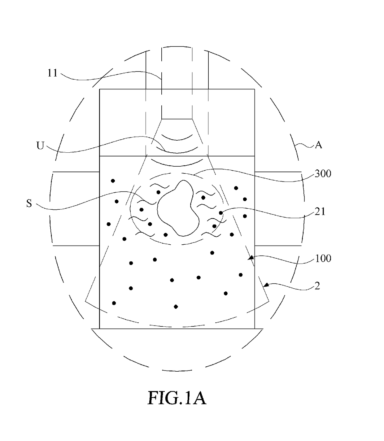
[0018]Please refer to FIG. 1 and FIG. 1A, wherein FIG. 1 is a schematic view of an imaging system for generating vibration region caused by ultrasound wave to obtain a plurality of optically-sectioned images in accordance with a preferred embodiment of the present invention, and FIG. 1A is a partially enlarged view of FIG. 1.

[0019]As shown, the imaging system 1 for generating vibration region caused by ultrasound wave to obtain a plurality of optically-sectioned images in accordance with a preferred embodiment of the present invention (hereinafter the “imaging system”) comprises an ultrasound device 11, a translational stage 12, a laser generating device ...


PUM

PropertyMeasurementUnit
thicknessaaaaaaaaaa
thicknessaaaaaaaaaa
elasticityaaaaaaaaaa

Abstract

An imaging system is configured for generating vibration region caused by ultrasound wave thereby to obtain a plurality of optically-sectioned images. In the imaging system, a stage is operable to be moved along a plurality of scanning imaging positions, and applied to deposit an object with at least one scattering material. When the object receives an ultrasound wave, a shear wave is generated to displace the scattering material thereby to form a vibration region. A laser generating device is configured to transmit a laser beam, which penetrates the vibration region to form a speckle pattern and focused at a focusing position. An optical imaging device is set at the focusing position to receive the laser beam to generate a plurality of scanning optically-sectioned images with respect to the scanning imaging positions.

Description

[0001]This application claims the benefit of Taiwan Patent Application Serial No. 106105747, filed Feb. 21, 2017, the subject matter of which is incorporated herein by reference.BACKGROUND OF INVENTION1. Field of the Invention[0002]The present invention is related to an imaging system for generating vibration region caused by ultrasound wave to obtain optically-sectioned images, and more particularly is related to an imaging system for generating vibration region caused by ultrasound wave to obtain optically-sectioned images and processing these images to generate the elasticity image.2. Description of the Prior Art[0003]With the development of technologies, the improvement of medical technologies may increase the lifespan of humans. In many diseases, such as cancer, stiff nodules were formed in the biological tissue. For this reason, palpation was widely used in clinical physical examinations for sensing the degree and distribution of the stiffness of biological tissues. However, t...

Claims


Application Information

Patent Timeline
Patent Type & Authority Applications(United States)
IPC IPC(8): A61B5/00A61B8/00A61B8/08G01N21/49
CPCA61B5/0082G01N21/49A61B8/485A61B8/4444G01N21/1717G01N21/45G01N21/4795G01N2021/479G01N29/2418A61B5/0097G01H9/008G01N29/00
Inventor LI, PAI-CHICHAO, PEI-YU
Owner NAT TAIWAN UNIV
Why Eureka
Try Eureka