

Conveyor drive and system for unit handling conveyors
- Summary
- Abstract
- Description
- Claims
- Application Information
AI Technical Summary
Benefits of technology
Problems solved by technology
Method used
Image

Examples
Embodiment Construction
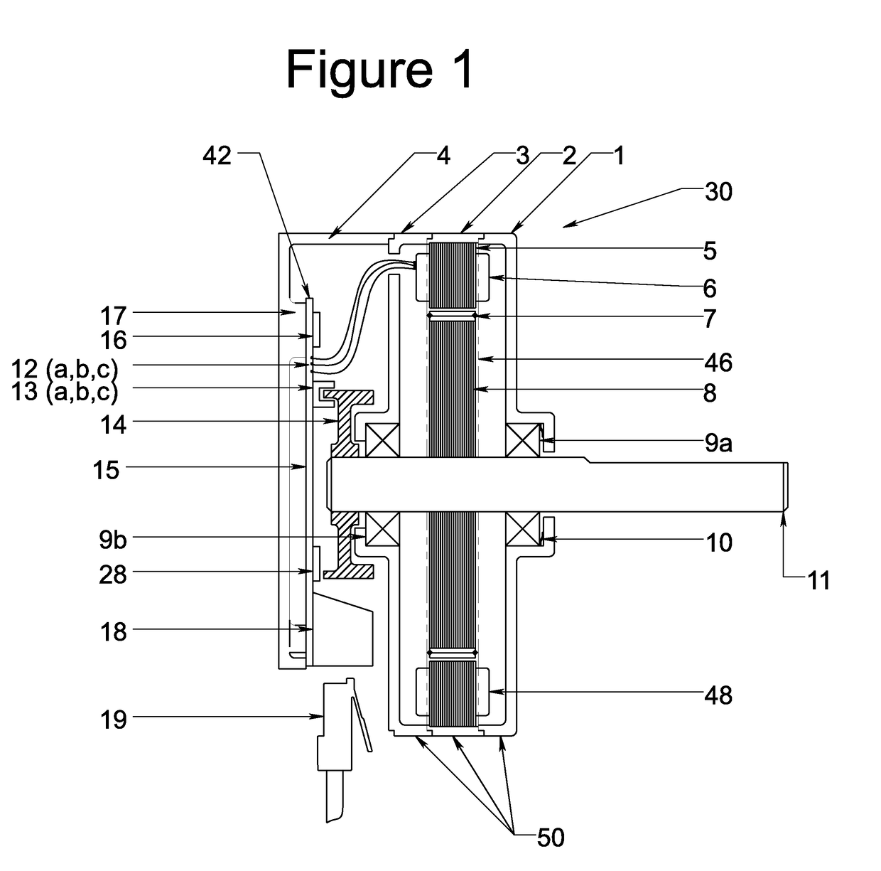
[0037]Overview.
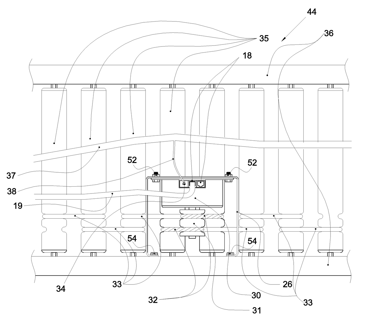
[0038]A motor assembly 30 in accordance with an embodiment of the present invention is shown in FIG. 1. The motor assembly 30 may be integrated into a unit handling roller conveyor system, for example, into roller conveyor system 44 (a portion of which is shown in part in FIG. 3), roller conveyor system 444 (a portion of which is shown in FIG. 7), roller conveyor system 544 (a portion of which is shown in FIG. 8) or roller conveyor system 644 (a portion of which is shown in FIG. 9). In each of these embodiments, the roller conveyor system includes a pair of conveyor frames 36, 436, 536, 636 that support conveyor rollers 35, 435, 535, 635. In these embodiments, the motor assembly 30, 430, 530, 630 is mounted below the conveyor rollers 35, 435, 535, 635 and between the conveyor frames 36, 436, 536, 636. The motor assembly 30, 430, 530, 630 is operatively coupled to the conveyor rollers 35, 435, 535, 635 by a plurality of belts 32 / 33, 432 / 433, 532 / 533. 632 / 633.
[0039]The ...
PUM
 Abstract
Description
Claims
Application Information