Ladar Pulse Deconfliction Apparatus
- Summary
- Abstract
- Description
- Claims
- Application Information
AI Technical Summary
Benefits of technology
Problems solved by technology
Method used
Image
Examples
Embodiment Construction
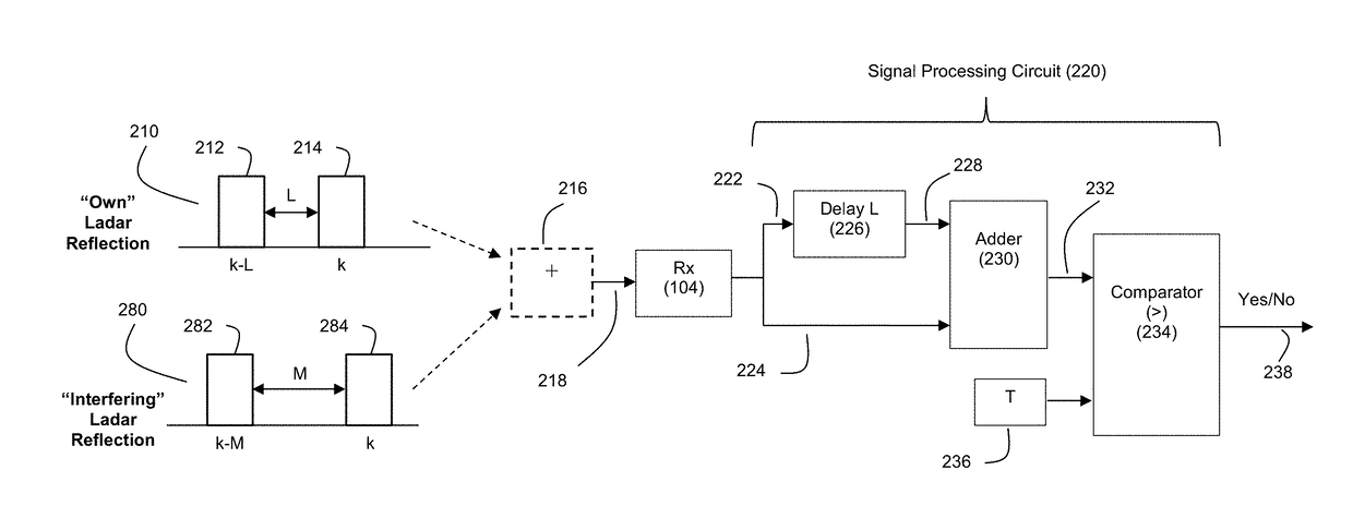
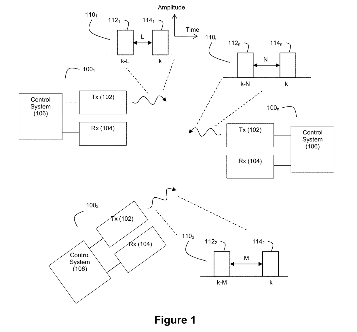
[0032]FIG. 1 depicts an example environment where there are multiple ladar systems 100 (e.g., 1001, 1002, . . . 100n) that transmit ladar pulses. Each ladar system 100 comprises a ladar transmitter 102, a ladar receiver 104, and a control system 106. Each ladar transmitter 102 is configured to generate and transmit ladar pulses into the environment. Each ladar receiver 104 is configured to receive and detect a light signal that may include ladar pulse reflections. As noted above, this received signal may also include noise such as interfering pulses / pulse reflections from other ladar systems. Each control system 106 can be configured to control how its corresponding ladar transmitter 102 and ladar receiver 104 operate. Examples of suitable ladar systems 100 are disclosed and described in greater detail in U.S. patent application Ser. No. 62 / 038,065, filed Aug. 15, 2014; and U.S. Pat. App. Pubs. 2016 / 0047895, 2016 / 0047896, 2016 / 0047897, 2016 / 0047898, 2016 / 0047899, 2016 / 0047903, 2016 / ...
PUM
 Abstract
Description
Claims
Application Information
 - R&D
- Intellectual Property
- Life Sciences
- Materials
- Tech Scout
- Unparalleled Data Quality
- Higher Quality Content
- 60% Fewer Hallucinations
Browse by: Latest US Patents, China's latest patents, Technical Efficacy Thesaurus, Application Domain, Technology Topic, Popular Technical Reports.
© 2025 PatSnap. All rights reserved.Legal|Privacy policy|Modern Slavery Act Transparency Statement|Sitemap|About US| Contact US: help@patsnap.com


