
External antenna for vehicle

a technology for external antennas and vehicles, applied in the direction of resonant antennas, substantially flat resonant elements, independent non-interacting antenna combinations, etc., can solve the problems of data distortion, limited antenna size to which sharkfin antennas mounted on the exterior of vehicles can grow, and reduce the radiation efficiency of antennas. , the effect of increasing the antenna frequency bandwidth

Active Publication Date: 2018-08-23
MOLEX INC
View PDF2 Cites 4 Cited by
  • Summary
  • Abstract
  • Description
  • Claims
  • Application Information

AI Technical Summary

Benefits of technology

This patent aims to solve the technical problem of improving the radiative performance of external antennas for vehicles by increasing frequency bandwidth and minimizing signal interference between antennas. It also aims to simplify the design process and reduce manufacturing costs by arranging multiple antennas in a single housing. The coupling patch, which helps find an optimal location for mutual interference between the antennas, enables improved transmission speed and increases antenna efficiency and bandwidth. The use of elastically connected radiating bodies for multiple frequency bands enhances power supply resilience against physical impacts.

Problems solved by technology

However, previously, when the two kinds of LTE antennas (main, diversity) have been added in the narrow interior of the sharkfin antenna, especially in the low frequency band (700 MHz-1 GHz), signal interference has been severe, leading to data distortion and impaired data transmission speed.
In addition, the problem has arisen of the limitations on the size to which the sharkfin antenna mounted on the exterior of a vehicle can grow, in view of the need to keep all of the antennas covering a plurality of frequency bands within a single sharkfin antenna.
In addition, as electric power has been supplied by soldering the antenna contacts to a circuit board, there has been the problem of power supply and inadequate electrical contact at the solder sites due to external impact.

Method used


Image

  • External antenna for vehicle
  • External antenna for vehicle
  • External antenna for vehicle

Examples


Embodiment Construction

[0046]Hereinbelow, preferred embodiments of this disclosure will be explained in detail with reference to the attached diagrams. Please note that in describing this disclosure, the detailed explanation is omitted of functions and components which are common knowledge and are judged to unnecessarily obscure the core intent of the disclosure.

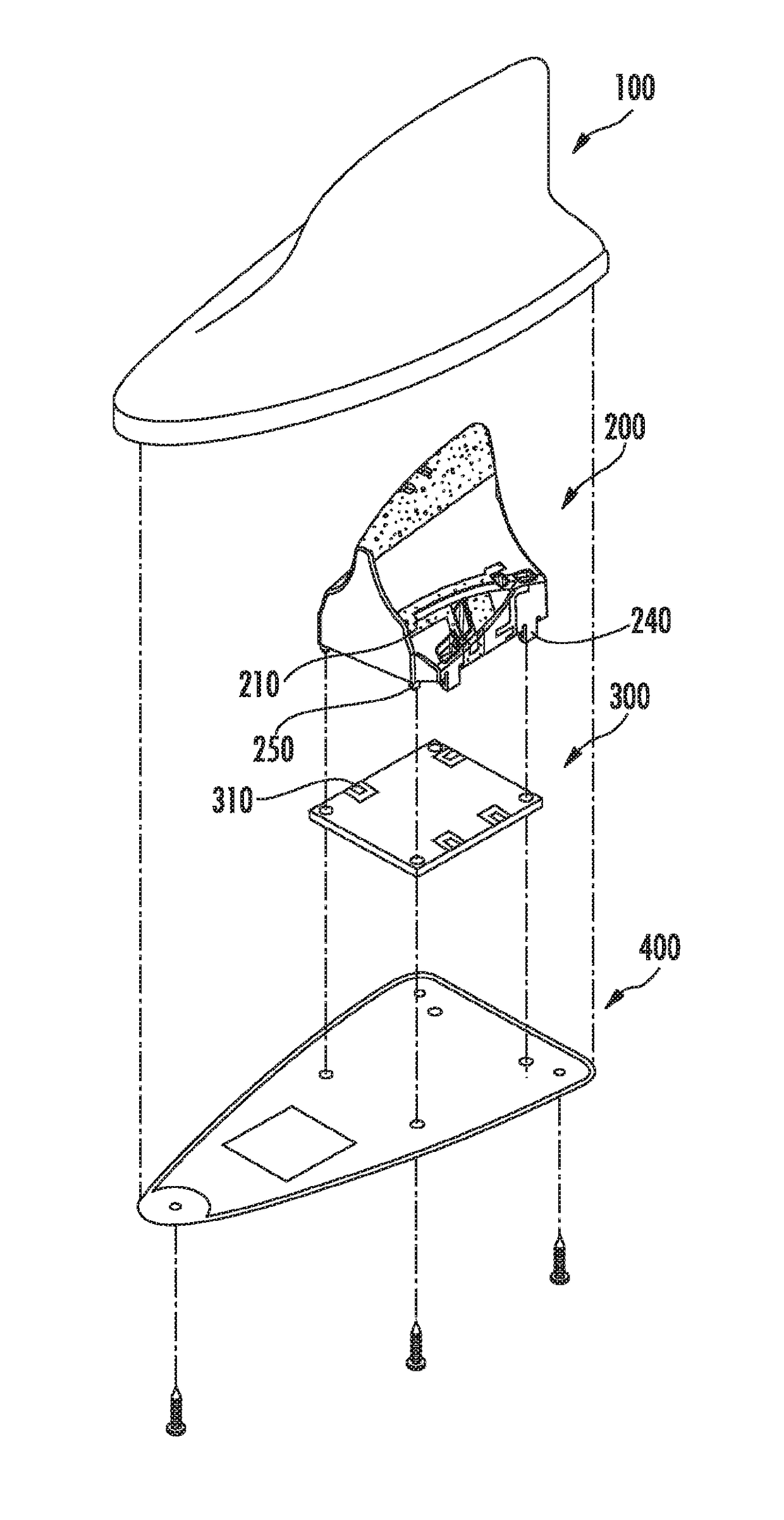
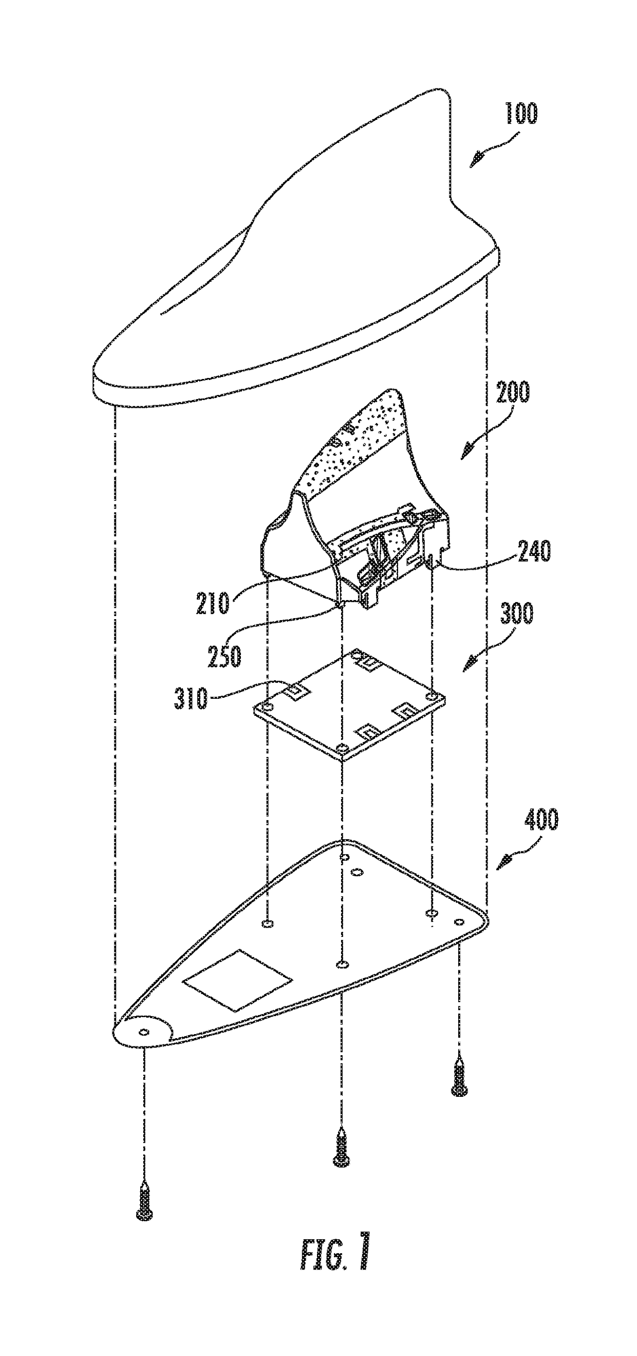
[0047]FIG. 1 is an exploded perspective view of the external antenna for vehicle use according to a preferred embodiment of this disclosure.

[0048]As shown in FIG. 1, the external antenna for vehicle use according to a preferred embodiment of this disclosure may comprise a case 100, housing 200, circuit board 300, and base 400.

[0049]The case 100 is formed in a triangular shape that tapers toward the top, e.g. in the shape of a shark fin, and is open at the bottom. The case 100 may be formed in various shapes in addition to a shark-fin shape.

[0050]The housing 200 is inserted via the open bottom of the case 100. The housing 200 is formed in a shape c...


PUM


Abstract

An antenna is disclosed wherein a plurality of antennas are combined in a single housing, whereby antenna radiation performance can be improved by increasing frequency bandwidth while minimizing signal interference between antennas. The antenna has a case, a housing, a circuit board, and a base. The case has an open bottom. The housing, formed in a shape corresponding to the interior surface of the case and inserted into the interior of the case, has a plurality of radiating bodies that send and receive signals in a plurality of frequency bands, and a coupling patch that increases frequency bandwidth and minimizes signal interference between radiating bodies. The board is mounted in the case and whereon a feeding pad is furnished that is electrically connected to the radiating bodies. The base is mounted on the board so as to couple to the case and block to open bottom of the case.

Description

RELATED APPLICATIONS[0001]This application claims priority to Korean Application No. 10-2015-0117469, filed Aug. 20, 2015, which is incorporated herein by reference in its entiretyTECHNICAL FIELD[0002]This disclosure relates to an antenna for use in a vehicle, and more specifically to an external antenna for a vehicle that is mounted on the exterior of the vehicle and receives or transmits radio waves.BACKGROUND ART[0003]With the development of wireless communications, various kinds of communication devices have been installed in vehicles, including radios, navigation, DMB, etc.; and for these devices, antennas also have to be mounted.[0004]As numerous antennas have thus come to be installed on the inside and outside of vehicles, because of the vehicle's shielding effect tending to reduce the reception rate for internal antennas, antennas have been mounted on the outside of the vehicle, and external antennas in the shape of a shark fin, which is an attractive shape with low air resi...

Claims


Application Information

Patent Timeline
Patent Type & Authority Applications(United States)
IPC IPC(8): H01Q1/38H01Q1/12H01Q1/32H01Q21/28H01Q9/04
CPCH01Q1/38H01Q1/1214H01Q1/3275H01Q21/28H01Q9/0407H01Q1/36
Inventor JEONG, DAE HYEONOH, CHANG HEONJEONG, HU BONGYOO, JU BONG
Owner MOLEX INC
Learn More