
Repetitive IO Structure in a Phy for Supporting C-Phy Compatible Standard and/or D-Phy Compatible Standard

a phy and io technology, applied in the field of io architecture in physical layers, can solve the problems of c-phy being more susceptible to noise, and achieve the effects of reducing the effort of a designer, reducing measurement time, and reducing performance differences

Active Publication Date: 2018-08-23
M31 TECH
View PDF0 Cites 4 Cited by
  • Summary
  • Abstract
  • Description
  • Claims
  • Application Information

AI Technical Summary

Benefits of technology

This patent is about a new type of circuit that can support both D-PHY and C-PHY technologies, which are commonly used in data transmission. With this design, multiple blocks can be used to meet different bandwidth requirements, which helps to achieve a symmetrical arrangement of pads that reduces performance differences between different lanes of D-PHY. This reduces the effort required for circuit design and verification, resulting in more efficient and accurate testing. The patent also describes the use of shielding wires to reduce interference between adjacent trios of C-PHY, and the use of LDO power domains to prevent power interference from other adjacent trios. Overall, these technical improvements enhance the performance and reliability of the circuit, making it more efficient and reliable for high-speed data transmission.

Problems solved by technology

FIG. 5b shows another traditional pad arrangement 500B with die pads enclosed in blocks 550, 551, 552, 553, 554 in which pad(s) 555, 556 are reserved to mitigate crosstalk in C-PHY; however, the asymmetrical pad arrangement of the IO blocks 550, 551, 552, 553, 554 is disadvantageous to D-PHY such that it will cause performance issues, such as jitter measurement and / or troublesome design between different lanes of D-PHY.
Furthermore, from SNR point of view, C-PHY will be more susceptible to noise due to the fact that each C-HPY trio uses three single-ended wires for transmission.

Method used


Image

  • Repetitive IO Structure in a Phy for Supporting C-Phy Compatible Standard and/or D-Phy Compatible Standard
  • Repetitive IO Structure in a Phy for Supporting C-Phy Compatible Standard and/or D-Phy Compatible Standard
  • Repetitive IO Structure in a Phy for Supporting C-Phy Compatible Standard and/or D-Phy Compatible Standard

Examples


Embodiment Construction

[0052]The detailed explanation of the present invention is described as following. The described preferred embodiments are presented for purposes of illustrations and description, and they are not intended to limit the scope of the present invention.

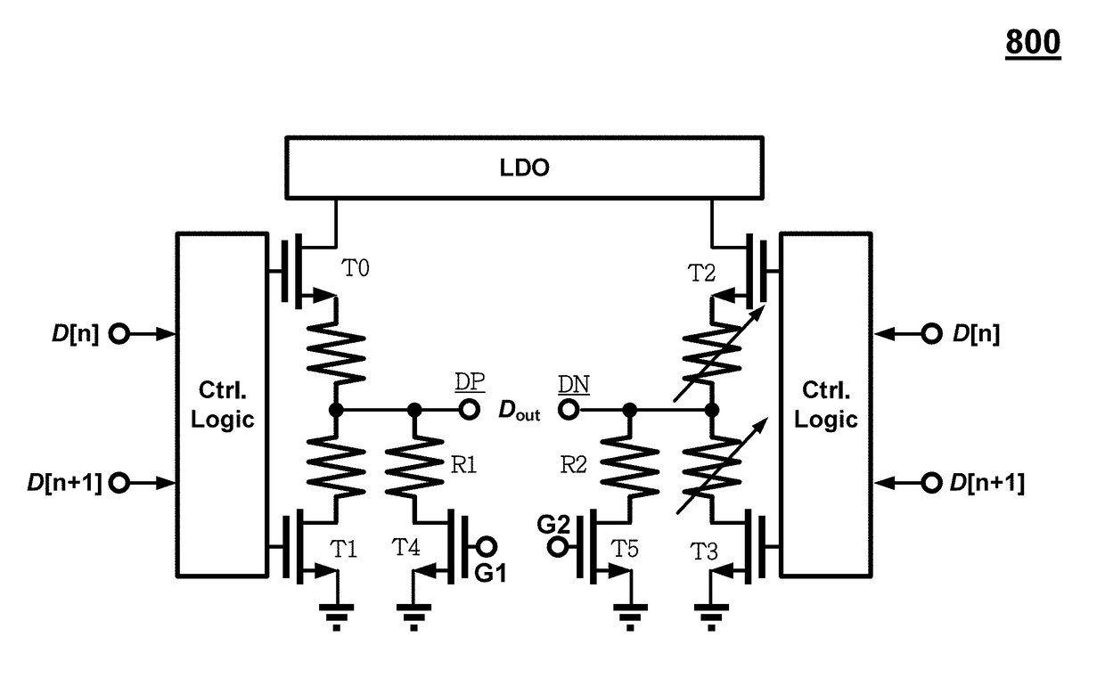
[0053]The present invention discloses a circuit in a physical unit (PHY), the circuit operated in C-PHY mode comprising two trios and a combo wire therebetween, wherein each of said trios includes three wires, and wherein the combo wire is configurable as floating, grounded or any dc voltage to act as shielding. In one embodiment, a circuit in a physical unit (PHY) comprises two trios and a shielding wire therebetween, wherein each of said trios includes three wires; and wherein said combo wire is configurable as a signal wire when the circuit is operating in a first mode (D-PHY). The shielding wire is either floating, grounded or at any dc voltage for reducing a signal interference between said two adjacent trios when C-PHY is used.

[005...


PUM

PropertyMeasurementUnit
dc voltageaaaaaaaaaa
poweraaaaaaaaaa
speedaaaaaaaaaa

Abstract

A circuit in a physical unit (PHY) is disclosed, the circuit comprising two trios and a combo wire therebetween, wherein each of said trios includes three wires, and wherein said combo wire is configurable as a signal, floating, or any dc voltage, furthermore, a Quad-IO block is designed for transmit data in two D-PHY lanes with the combo wire configured as a signal wire or a C-PHY trio with the combo wire configured as a shielding wire, such that the same Quad-IO block can be instantiated multiple times in a physical unit for meeting different bandwidth requirements as well as for placing pads along a same direction for preventing performance difference between D-PHY lanes or C-PHY trios.

Description

CROSS-REFERENCES TO RELATED APPLICATIONS[0001]This application claims the benefit of U.S. Provisional Patent Application No. 62 / 461,247 filed on Feb. 21, 2017, which is hereby incorporated by reference herein and made a part of specification.BACKGROUND OF THE INVENTION1. Field of the Invention[0002]The invention relates to IO architecture in physical layer and, in particular, but not exclusively, to multi-wire pad arrangement in the physical layer.2. Description of the Prior Art[0003]The Phy Working Group of the MIPI alliance has developed three specifications for high-speed physical layer designs to support multiple application requirements. The D-PHY standard was developed primarily to support camera and display applications using differential signals for transmitting data. The C-PHY standard is based on 3-Phase symbol encoding scheme delivering 2.28 bits per symbol over 3-wire trios, and targeting 2.5 Giga symbols per second. C-PHY has many characteristics in common with D-PHY as...

Claims


Application Information

Patent Timeline
Patent Type & Authority Applications(United States)
IPC IPC(8): H03K5/1252H01B11/00G06F13/40
CPCH03K5/1252G06F13/4027H01B11/00G06F13/28H04B3/02G06F13/4072H04L25/0272H04L25/00
Inventor WANG, HUAI-TEHUNG, CHIH CHIEN
Owner M31 TECH
Learn More