
Trim strip assembly for vehicle and method of manufacturing same

a technology for trim strips and vehicles, which is applied in the field of trim strips for vehicles, can solve the problems of insufficient method of conventional decorative trim, high material cost, and high cost of thin metal sheets to trim, and achieves easy and inexpensive bonding, time- and cost-saving, and time- and cost-saving effects

Active Publication Date: 2018-08-30
HENNIGES AUTOMOTIVE SEALING SYST NORTH AMERICA
View PDF0 Cites 7 Cited by
  • Summary
  • Abstract
  • Description
  • Claims
  • Application Information

AI Technical Summary

Benefits of technology

The present invention provides a cost-effective way to make a trim strip assembly. The assembly is made up of decorative sheets that can be easily attached to the trim portion using simple methods. The trim portion is coextruded with the decorative trim member to efficiently form and bond them together. The coupling members are formed at the same time as the trim members and are coupled to each other during the formation of the trim portion. This makes the trim strip assembly quick and easy to manufacture, using cheap materials, and allows for the production of several trim strip assemblies in a short amount of time. This allows for the production of low-cost trim strip assemblies, which provides a competitive advantage in the market.

Problems solved by technology

Conventional decorative trim is manufactured using inadequate methods, especially in terms of time and cost.
Applying sheets of thin metal to trim is expensive in terms of both material costs for sheets of thin metal and processing costs for bonding the metal to sealing elements of the trim.
Conventional methods of applying decorative films to sealing elements of trim including multiple sealing elements is also cost inefficient, as the sealing elements are each manufactured separately, decorative film is applied to each of the sealing elements separately using methods such as heat bonding, and the sealing elements are coupled to one another in a further process.
Thus, conventional techniques are inefficient in terms of both time and money.

Method used


Image

  • Trim strip assembly for vehicle and method of manufacturing same
  • Trim strip assembly for vehicle and method of manufacturing same
  • Trim strip assembly for vehicle and method of manufacturing same

Examples


Embodiment Construction

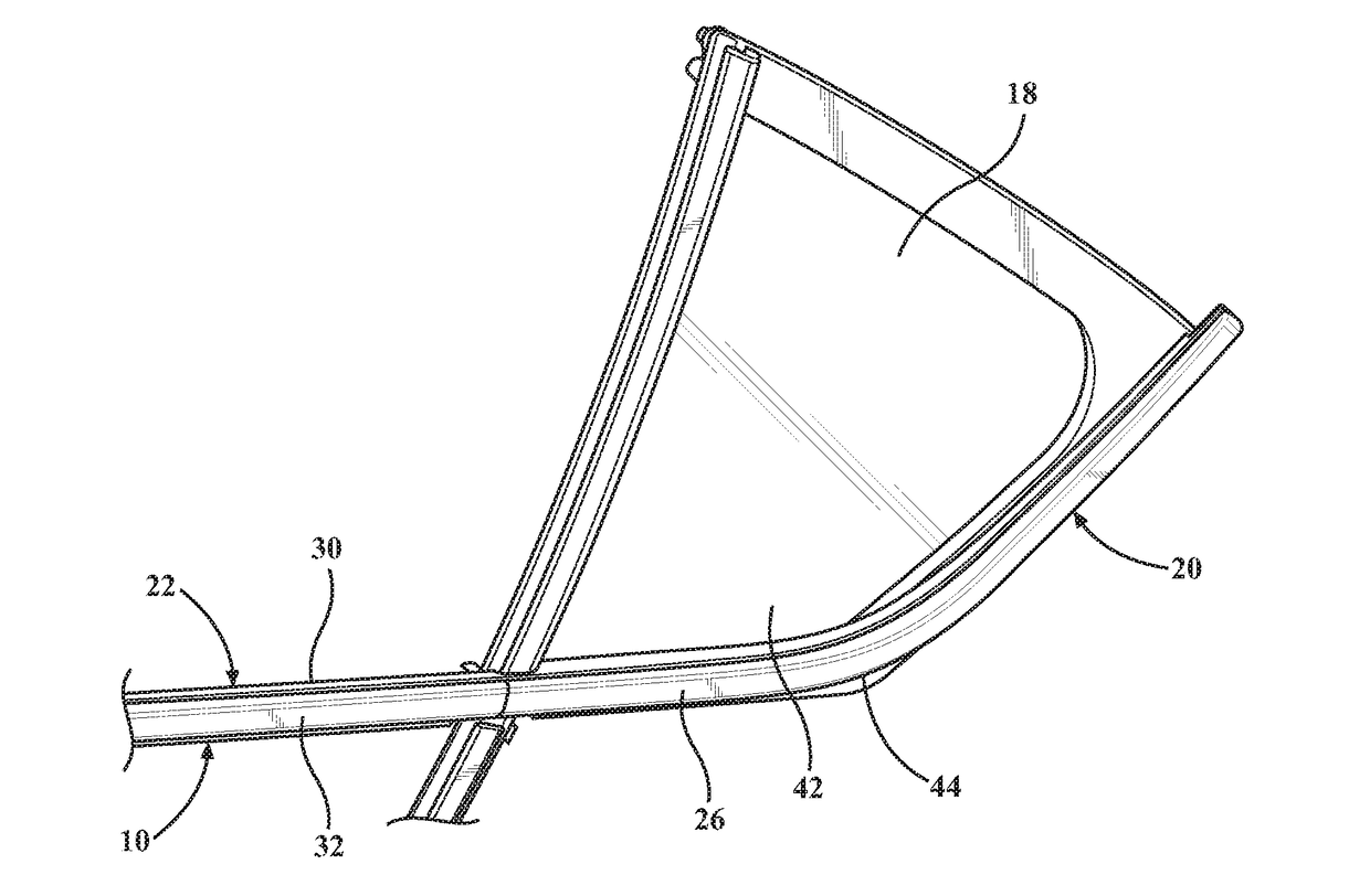
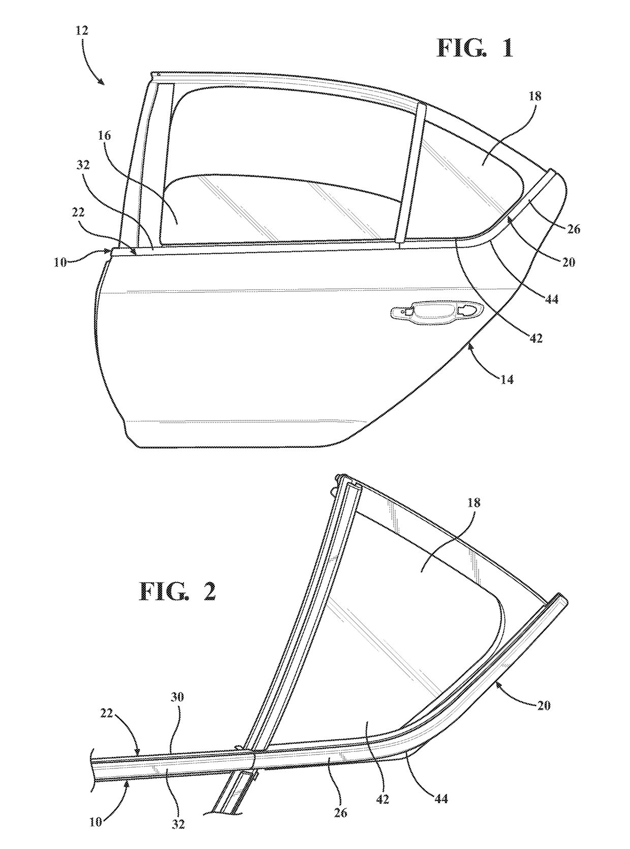
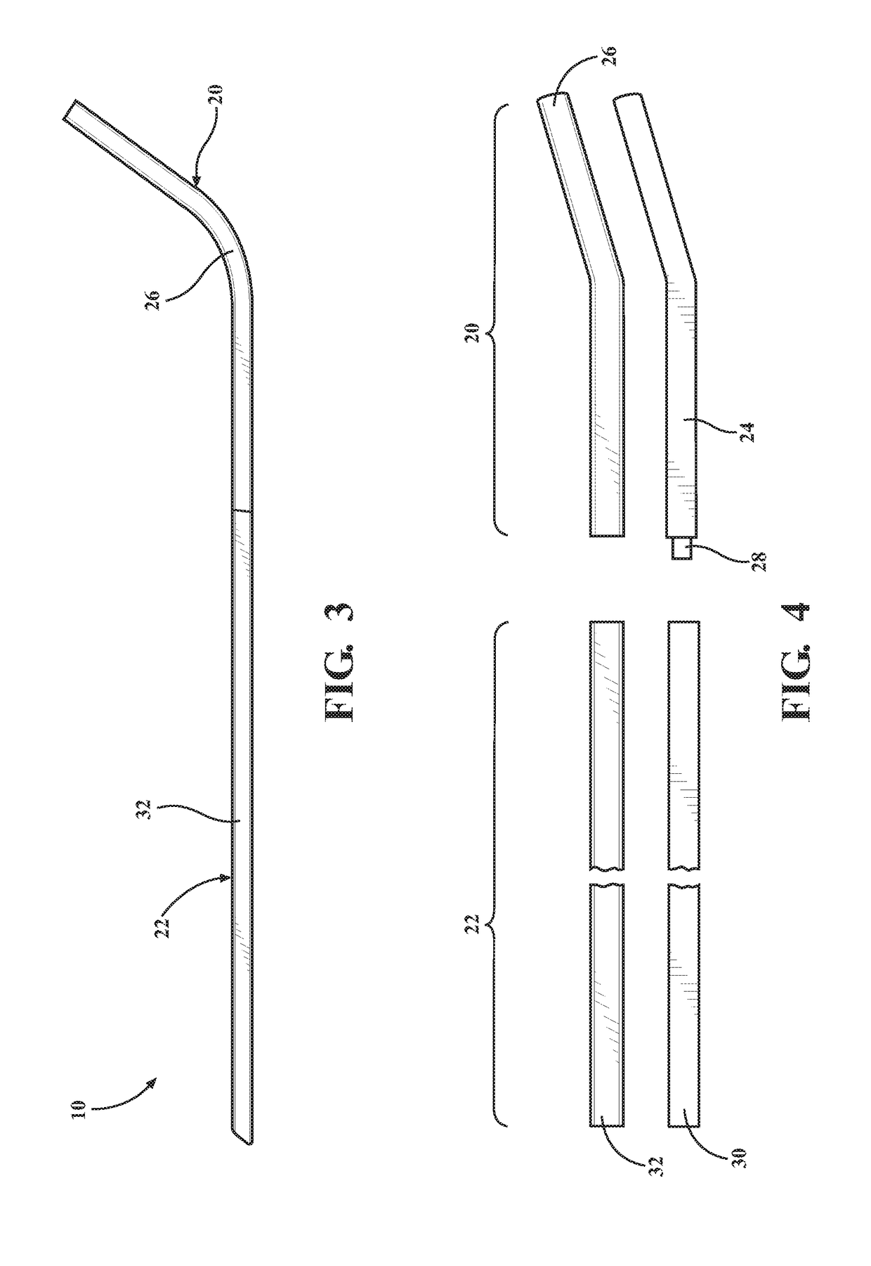
[0028]Referring to the Figures, wherein like numerals indicate like or corresponding parts throughout several views, aspects of a trim strip assembly 10 for a vehicle and method of manufacturing the same are provided.

I. Assembly Description

[0029]FIG. 1 illustrates an embodiment of a door assembly 12 for a vehicle. The door assembly 12 includes a door frame 14, a movable window 16, a fixed window 18, and a trim strip assembly 10.

[0030]The door frame 14 is any door frame for a vehicle suitable for supporting both the movable window 16 and the fixed window 18. The door frame 14 can be a door frame for a car, truck, sports utility vehicle, or any other suitable vehicle. According to some embodiments, the trim strip assembly 10, or trim strip, partially covers and seals interfaces between the door frame 14, the movable window 16, and the fixed window 18. The trim strip assembly 10 also provides a desirable appearance.

[0031]The movable window 16 is coupled to the door frame 14. The movabl...


PUM

PropertyMeasurementUnit
polymericaaaaaaaaaa
rigidaaaaaaaaaa
flexibleaaaaaaaaaa

Abstract

A trim strip assembly for a vehicle and method of making the same is provided. The trim strip assembly includes a first trim portion. The first trim portion has a polymeric base and a first decorative member bonded to the polymeric base. The polymeric base is formed of polymeric material molded to the first decorative member. The polymeric base includes a first coupling member. A second trim portion has an extruded base and a second decorative member bonded to the extruded base. The extruded base and the second decorative member are coextruded. The extruded base includes a second coupling member. The first coupling member is bonded to the second coupling member to interconnect the first trim portion and the second trim portion.

Description

BACKGROUND1. Field of the Invention[0001]The subject invention relates to a trim strip assembly for a vehicle and method of manufacturing the same, and more specifically, wherein the trim strip assembly includes a first molded trim portion simultaneously formed and bonded to a second extruded trim portion.2. Description of Related Art[0002]Decorative trim is becoming increasingly popular for consumer vehicles, especially decorative trim having metallic, colored, or otherwise designed appearances. Decorative trim allows vehicle manufacturers to design vehicles having, for example, chrome-like trim and contributes an accented finish to visual design of the vehicles while providing sealing properties for windows of the vehicles. Conventional decorative trim is manufactured using inadequate methods, especially in terms of time and cost. Applying sheets of thin metal to trim is expensive in terms of both material costs for sheets of thin metal and processing costs for bonding the metal t...

Claims


Application Information

Patent Timeline
Patent Type & Authority Applications(United States)
IPC IPC(8): B60R13/02B60J5/04
CPCB60R13/0243B60J5/0402B60J5/0463B60R13/04B60J10/23B60J10/32B60J10/75B29C45/14409B29C69/02B29C48/001B29C48/16B60J10/15B29K2023/12B29K2709/08B29L2031/302B29L2031/3052B60J1/10B60R13/06B60J10/45B60J10/70B29C45/14434B60Y2410/123
Inventor HUSEK, PETRSLAVIK, DANIELGRUTER, ACHIM
Owner HENNIGES AUTOMOTIVE SEALING SYST NORTH AMERICA
Learn More