Accumulator assembly fixture

a technology for assembly fixtures and accumulators, applied in the direction of mechanical equipment, manufacturing tools, instruments, etc., can solve the problems of large pistons in cylinders, costly damage, cylinders can be scored or otherwise damaged, etc., to reduce and/or prevent inner thread damage, durable and reliable construction, and low manufacturing cost

Active Publication Date: 2018-09-13
REEL POWER LICENSING
View PDF0 Cites 7 Cited by
  • Summary
  • Abstract
  • Description
  • Claims
  • Application Information

AI Technical Summary

Benefits of technology

[0012]Therefore, it is an object of the present invention to provide a new and improved accumulator assembly apparatus, system and method for use that may provide a removable protective guide sleeve to reduce and or prevent damage to the inner threads of the accumulator during assembly.
[0013]It is a further object of the present invention to provide a new and improved accumulator assembly apparatus, system and method, which is of a durable and reliable construction and may be utilized in numerous types of applications.
[0014]An even further object of the present invention is to provide a new and improved accumulator assembly apparatus, system and method, which is susceptible to a low cost of manufacture, which accordingly is then susceptible to low prices of sale to the consuming industry, thereby making such a system economically available to those in the industry.

Problems solved by technology

The installation of a large piston in a cylinder such as that used in a subsea accumulator can be difficult, and if the piston is not inserted in the cylinder directly in line with the axis of the cylinder, the resulting damage is costly.
Cylinders can become scored or otherwise damaged along their inside bore, and oftentimes this damage renders the cylinder useless for its intended purpose.
This procedure is problematic, and often does not result in properly aligned piston to cylinder insertion, creating the potential for serious damage to the piston and cylinder assembly.
A similar problem exists when a large piston must be retracted and removed from a cylinder for service, replacement, or the like.

Method used


Image

  • Accumulator assembly fixture
  • Accumulator assembly fixture
  • Accumulator assembly fixture

Examples


Embodiment Construction

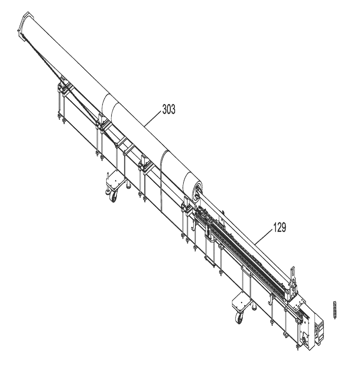
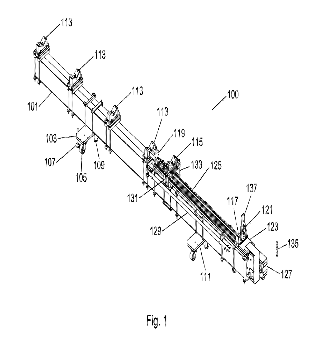
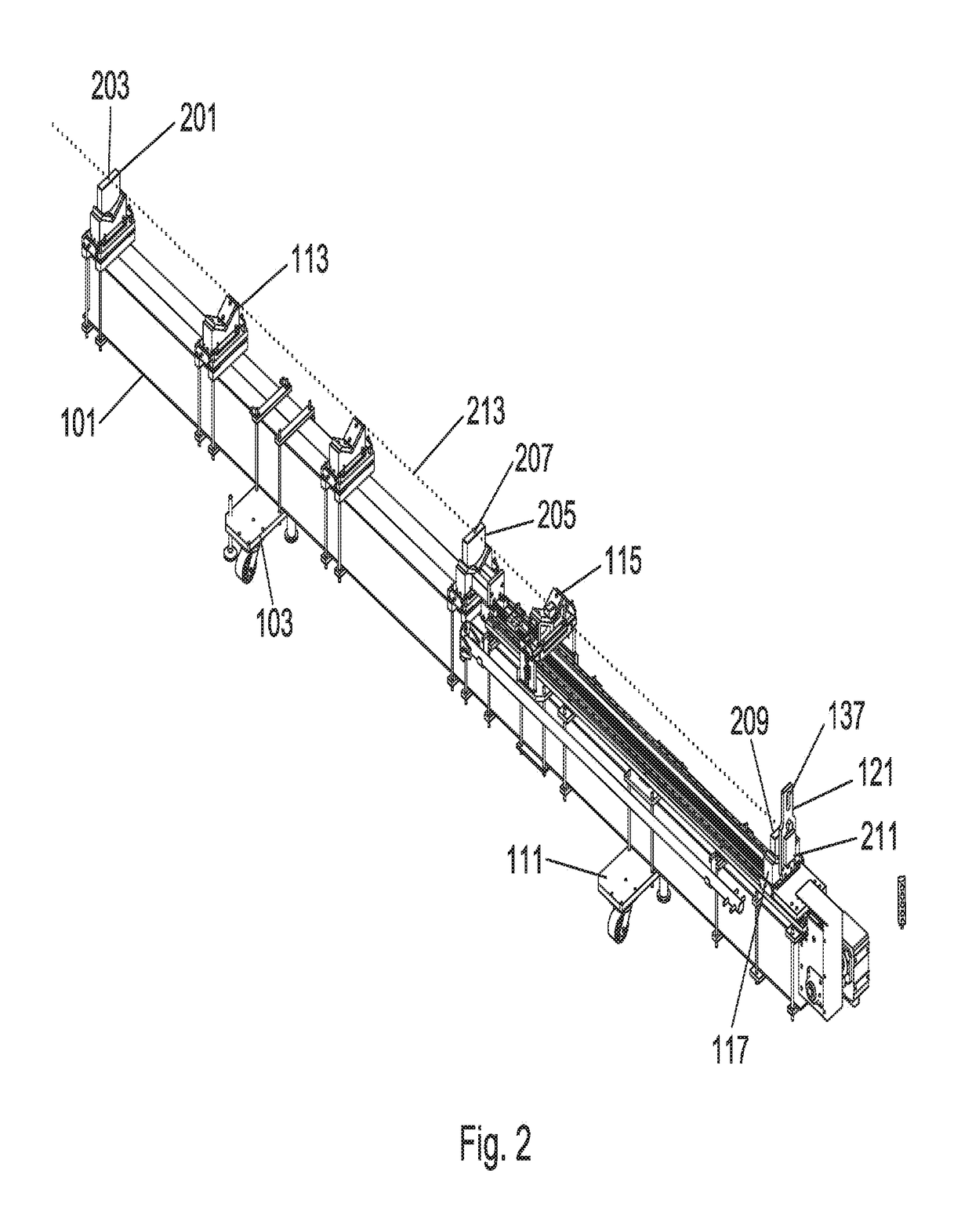
[0051]Referring to the illustrations, drawings, and pictures, reference character 100 generally designates a new and improved assembly fixture apparatus, system and method of using the same constructed in accordance with the present invention. Invention 100 is generally for the proper installation and extraction of large pistons in cylinder assemblies such as, but not limited to, those used for accumulators in deep water drilling operational and control systems. For purposes of convenience, the reference numeral 100 may generally be utilized for the indication of the invention, portion of the invention, preferred embodiments of the invention and so on. Throughout this specification, the terms accumulator assembly fixture, piston and cylinder assembly fixture and assembly fixture are used interchangeably herein. Each term referring to the present invention and the various embodiments described and envisioned herein.

[0052]There are various techniques for the design and construction of...


PUM

PropertyMeasurementUnit
lengthaaaaaaaaaa
structuresaaaaaaaaaa
shapeaaaaaaaaaa

Abstract

The present invention is an apparatus, system and method to properly align and install large pistons in cylinders that holds both the piston and cylinder being assembled, and has a number of alignment mechanisms such as but not limited to a laser.

Description

CROSS-REFERENCE TO RELATED APPLICATIONS[0001]The present application is a continuation-in-part of U.S. patent application Ser. No. 14 / 466,934, filed Aug. 22, 2014, currently pending, which claims benefit of U.S. Provisional Patent Application Ser. No. 62 / 006,606 filed on Jun. 2, 2014. Each of the applications listed above is hereby expressly incorporated herein by reference in their entirety.BACKGROUND OF INVENTION1. Field of the Invention[0002]In general, the present invention relates generally to alignment and installation fixtures and systems. More in particular, the present invention provides an assembly fixture for the proper installation of large pistons in cylinder assemblies such as those used for accumulators.2. Description of the Prior Art[0003]The installation of a large piston in a cylinder such as that used in a subsea accumulator can be difficult, and if the piston is not inserted in the cylinder directly in line with the axis of the cylinder, the resulting damage is c...

Claims


Application Information

Patent Timeline
Patent Type & Authority Applications(United States)
IPC IPC(8): B23P19/12B25B11/02B23P19/02B23Q3/10G01B11/27F15B1/04
CPCB23P19/12B25B11/02B23P19/022B23Q3/104G01B11/27F15B1/04F15B2201/60F15B1/24F15B2201/31F15B2201/605F15B2201/61F15B2201/615G01B11/272Y10T29/49394Y10T29/53Y10T29/53087Y10T29/53091
Inventor BUCKMINSTER, WILLIAM FRANKHENRY, JOSEPHWOLFE, GLENNWILKINS, JIMMYSCHMIDT, NATHAN
Owner REEL POWER LICENSING
Why Eureka
Try Eureka