Check patentability & draft patents in minutes with Patsnap Eureka AI!

Belt continuously variable transmission and failure determination method of the same

Inactive Publication Date: 2018-09-13
NISSAN MOTOR CO LTD
View PDF0 Cites 2 Cited by
  • Summary
  • Abstract
  • Description
  • Claims
  • Application Information

AI Technical Summary

Benefits of technology

The patent text describes a system that prevents the secondary pressure regulating valve from being incorrectly determined as failing when the input rotation speed sensor fails. This means that the valve can still be considered normal when it is working correctly.

Problems solved by technology

However, if the above-mentioned fail-safe control is executed in a CVT, when a rotation speed of an engine is low, a discharge amount of an oil pump driven by the engine decreases.
This causes an insufficient amount of oil supplied to a secondary pulley, and there may be a case where a secondary pressure does not rise up to an instruction pressure.
The execution of this control largely affects power performance of the vehicle; therefore, the execution of such control on the basis of an erroneous determination result is not preferable in some cases.

Method used


Image

  • Belt continuously variable transmission and failure determination method of the same
  • Belt continuously variable transmission and failure determination method of the same
  • Belt continuously variable transmission and failure determination method of the same

Examples


Embodiment Construction

[0020]The following describes an embodiment of the present invention by referring to the attached drawings.

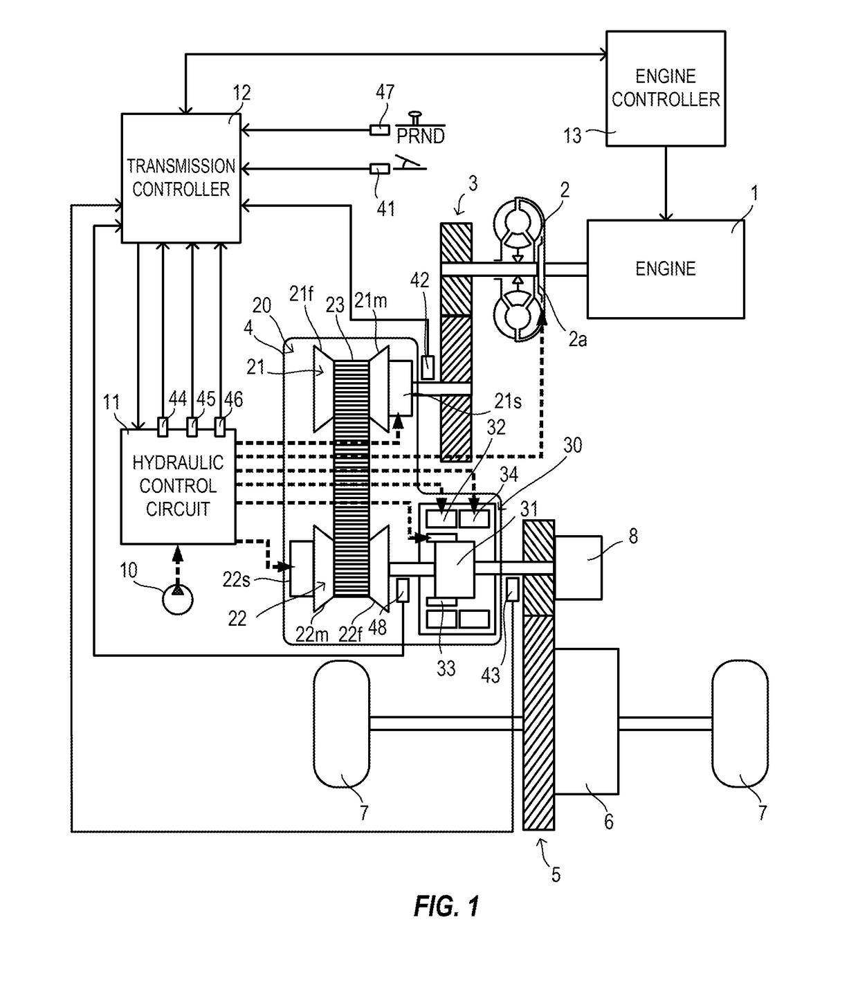
[0021]FIG. 1 is a schematic configuration diagram of a vehicle on which a belt continuously variable transmission according to the embodiment of the present invention is mounted. This vehicle includes an engine 1 as a power source. Output rotation of the engine 1 is transmitted to driving wheels 7 via a torque converter 2, a first gear train 3, a transmission 4, a second gear train 5, and a differential gear 6. A parking mechanism 8 that mechanically unrotatably locks an output shaft of the transmission 4 in parking is disposed on the second gear train 5.

[0022]The engine 1 is an internal combustion engine such as a gasoline engine and a diesel engine. An engine controller 13 controls a rotation speed and a torque of the engine.

[0023]The torque converter 2 includes a lock-up clutch 2a. When the lock-up clutch 2a is engaged, slip at the torque converter 2 disappears to ensure imp...


PUM


Abstract

A transmission controller is configured such that if an input rotation speed sensor is determined to have a failure, the transmission controller executes a fail-safe control and inhibits a failure determination of a secondary pressure solenoid valve on the basis of a difference between a secondary instruction pressure and a detected value by a secondary pressure sensor. The fail-safe control is configured to set the secondary instruction pressure to be a predetermined high pressure.

Description

TECHNICAL FIELD[0001]The present invention relates to a technique that determines a failure of such as a sensor and a solenoid valve in a belt continuously variable transmission (hereinafter referred to as “CVT”).BACKGROUND ART[0002]A CVT is constituted of a primary pulley and a secondary pulley whose groove widths are changeable and a belt stretched around between the primary pulley and the secondary pulley. Changing the groove widths of the respective pulleys changes contact radiuses between the belt and the respective pulleys, changing a speed ratio steplessly.[0003]The groove widths of the primary pulley and the secondary pulley are changed by primary pressure and secondary pressure supplied to respective oil chambers of these pulleys. By these hydraulic pressures, the belt is sandwiched by the primary pulley and by the secondary pulley.[0004]If a solenoid valve, which adjusts these hydraulic pressures, fails, a difference between an instruction pressure and an actual pressure b...

Claims


Application Information

Patent Timeline
IPC IPC(8): F16H61/12F16H61/00F16H61/662F16H61/70F16H37/02
CPCF16H61/12F16H61/0021F16H61/662F16H61/702F16H37/021F16H2037/023F16H2061/1232F16H2061/1284F16H2059/683F16H59/42F16H2061/1224F16H61/66
Inventor SUDO, TATSUYAITOU, YOUJIABE, KOSUKE
Owner NISSAN MOTOR CO LTD
Features
  • R&D
  • Intellectual Property
  • Life Sciences
  • Materials
  • Tech Scout
  • Unparalleled Data Quality
  • Higher Quality Content
  • 60% Fewer Hallucinations
Learn More