

A cartridge for pulse-separated variable turbine geometry turbochargers
- Summary
- Abstract
- Description
- Claims
- Application Information
AI Technical Summary
Benefits of technology
Problems solved by technology
Method used
Image

Examples
Embodiment Construction
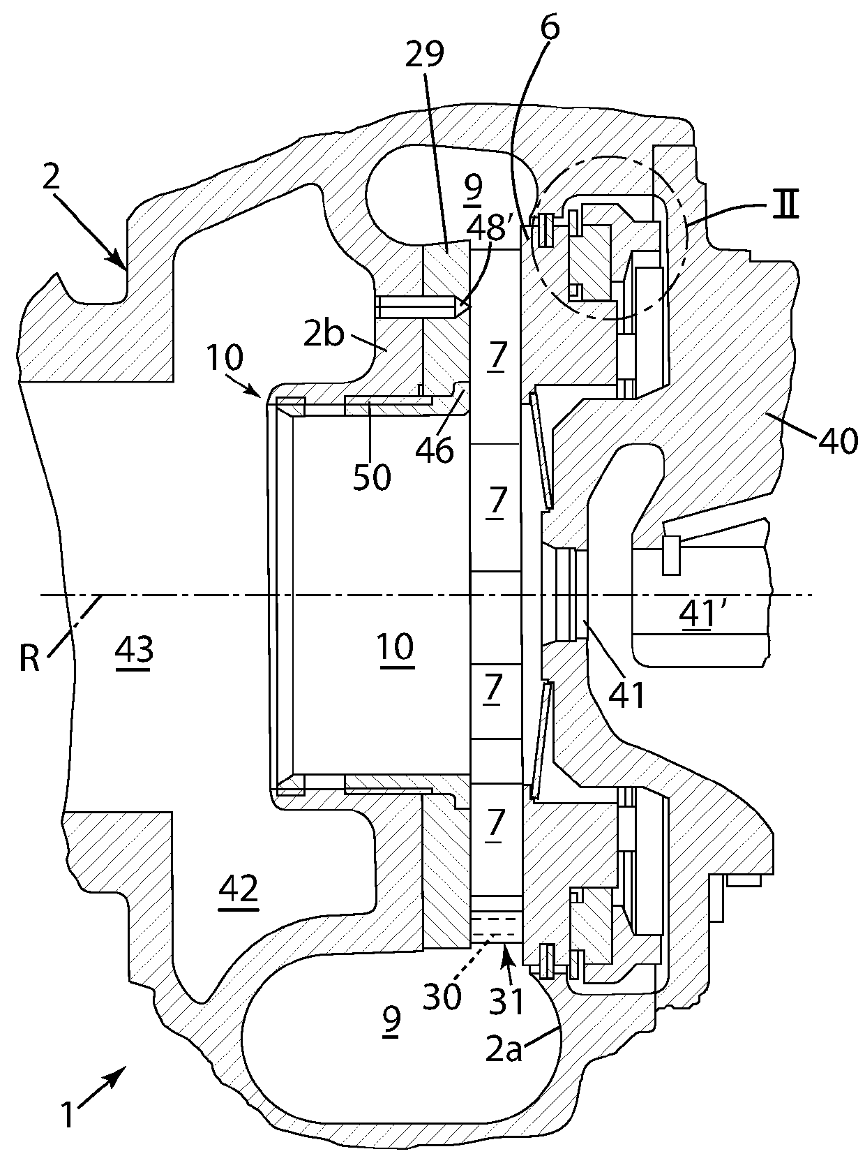
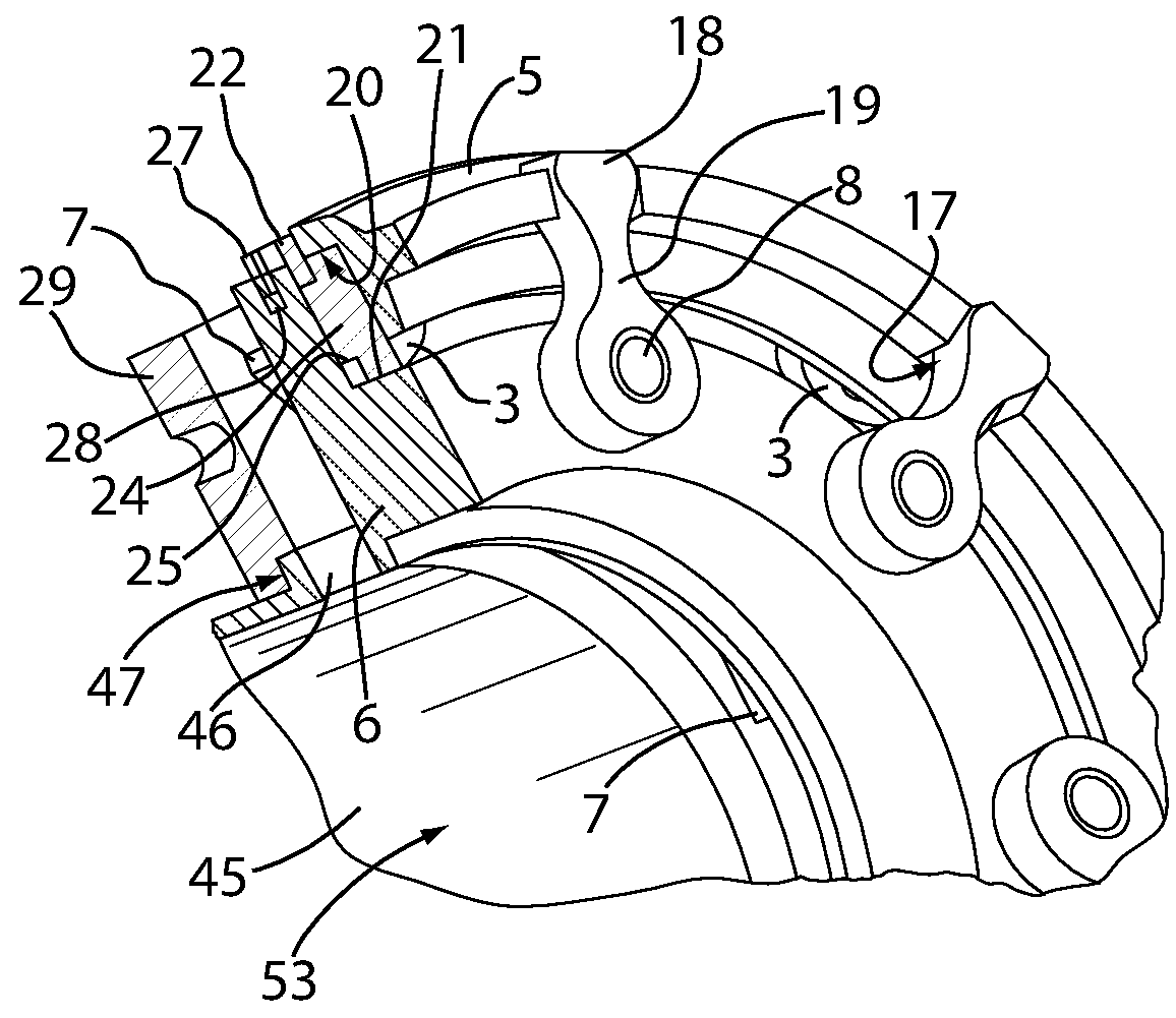
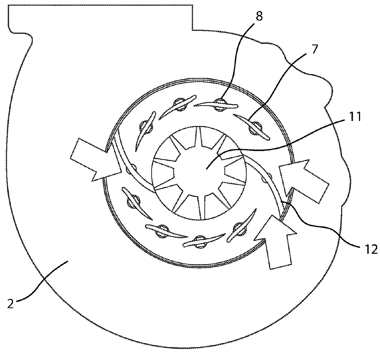
[0022]In FIG. 1, a part of a single volute turbine housing 2 of a turbocharger 1 is represented which, typically, comprises a peripheral supply channel or scroll or volute 9 for a fluid spirally wound around a central axis R. This fluid is then channeled inwards radially through a plurality of guiding vanes 7 arranged around a central axis R, to a turbine wheel (not shown) rotating about the central axis R. This turbine wheel is mounted, as is known, at the end of a rotor shaft (also not shown) which is supported in bearings 41 and 41′ situated within a bearing housing 40 that is releasably attached to the turbine housing 2 and fastened to it by bolts or V-clamp (not shown). In the case of a turbocharger, this shaft extends through this bearing housing 40 to a compressor wheel located within a compressor housing that is either releasably attached to the bearing housing or may he integrally formed with it. This compressor may be driven in a known manner by the turbine wheel in the tu...
PUM
 Abstract
Description
Claims
Application Information