Eureka AIR delivers breakthrough ideas for toughest innovation challenges, trusted by R&D personnel around the world.

Spinal Implant with Screw Retention and Removal Mechanisms

Inactive Publication Date: 2018-11-01
ADDITIVE INNOVATIONS
View PDF2 Cites 0 Cited by
  • Summary
  • Abstract
  • Description
  • Claims
  • Application Information

AI Technical Summary

Benefits of technology

The present invention is an orthopedic spinal cage that is inserted into a patient's spine. The cage has features such as threaded screws and a matting and lag feature to prevent the screws from coming out. The screws also provide a tactile event when they are inserted and a stepped feature for easy removal with minimal force. These features can be used in any medical application that requires the use of threaded screws.

Problems solved by technology

This application and device have received no federally sponsored research or development assistance.
In other instances of DDD, genetic factors or apoptosis can also cause the cells within the nucleus pulposus to emit toxic amounts of these cytokines and MMPs.
In some instances, the pumping action of the disc may malfunction (due to, for example, a decrease in the proteoglycan concentration within the nucleus pulposus), thereby retarding the flow of nutrients into the disc as well as the flow of waste products out of the disc.
This reduced capacity to eliminate waste may result in the accumulation of high levels of toxins that may cause nerve irritation and pain.
This hardware adds to the time, cost, and complexity of the procedure.
It also can result in tissue irritation when the cage's profile extends out of the disc space, thereby causing dysphonia / dysphagia in the cervical spine and vessel erosion in the lumbar spine.
In addition, the fixation hardware typically includes a secondary locking feature, which adds to the bulkiness of the implant and time required for the procedure.
Furthermore, existing fixation hardware may prevent the implantation of additional hardware at an adjacent location, and so require removal and potentially extensive revision of a previous procedure.

Method used


Image

  • Spinal Implant with Screw Retention and Removal Mechanisms
  • Spinal Implant with Screw Retention and Removal Mechanisms
  • Spinal Implant with Screw Retention and Removal Mechanisms

Examples


Embodiment Construction

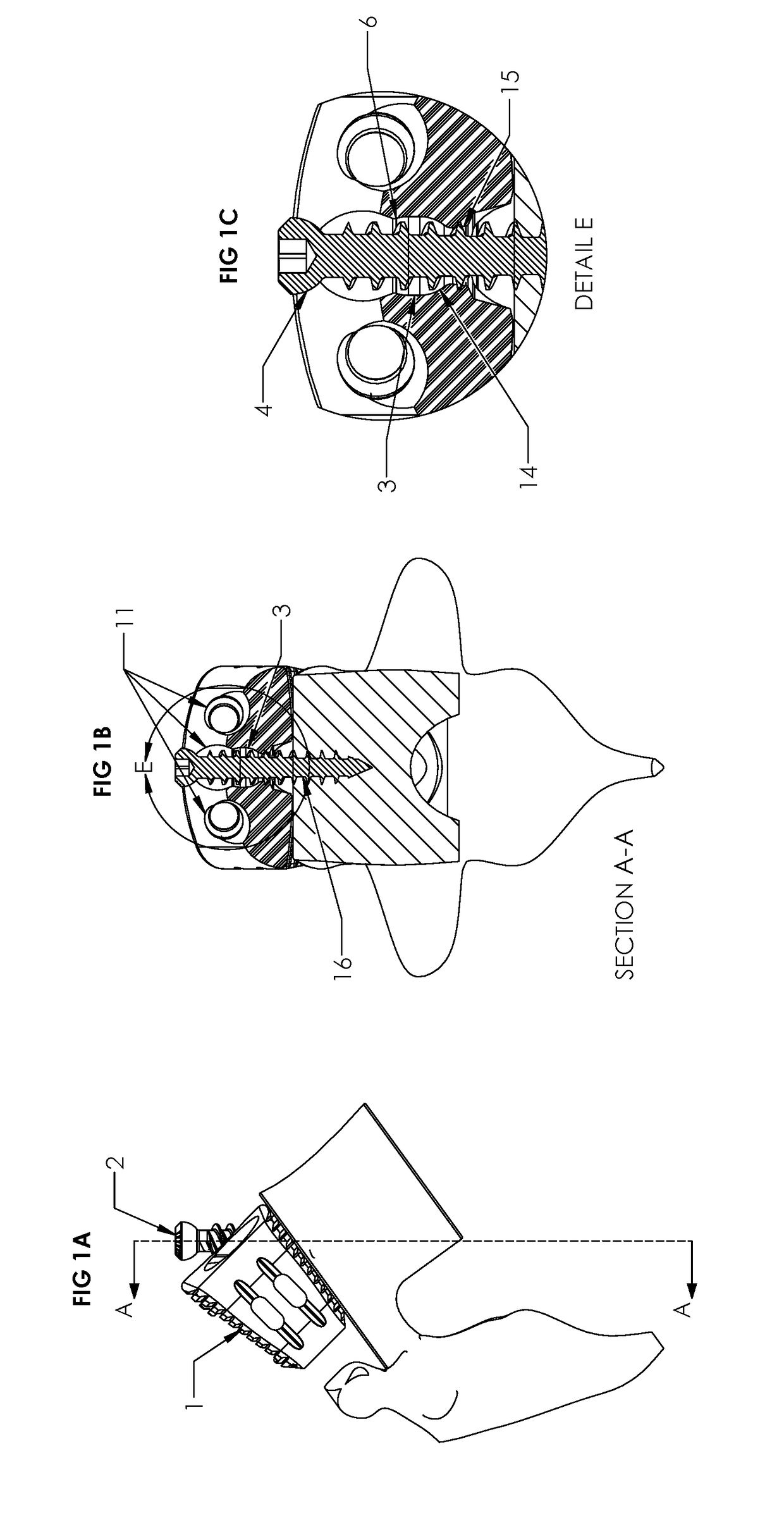
[0025]Referring to FIG. 1A, the interbody implant consists of a polymer spacer body 1 and a plurality of bone screws 2 used to secure the polymer implant 1 to the surrounding vertebral bodies 13.

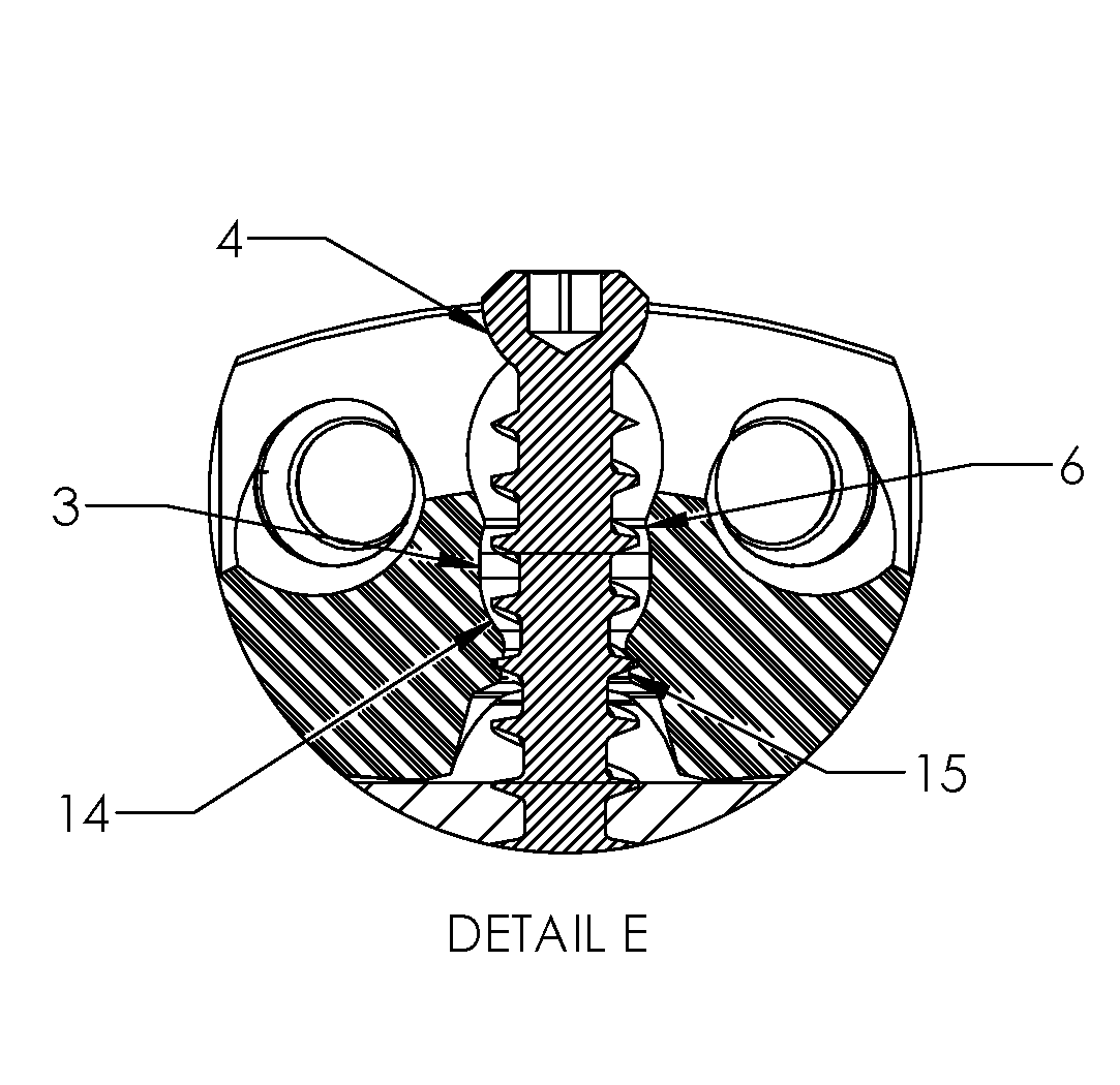
[0026]Referring to FIGS. 1B& C apertures 11 in the polymer implant 1 are fabricated with a cavity 3 designed to allow passage of the threaded portion 16 of the bone screw 1 and to capture and accommodate the hemispherical shaped head 4 of the bone screw 2.

[0027]One opening of the cavity 3 has an annular feature 6 that is smaller in diameter than the hemispherical diameter of the bone screw 4 head. An opposing opening in the cavity 3 has a spherical shaped surface 14 and reduced diameter passage 15.

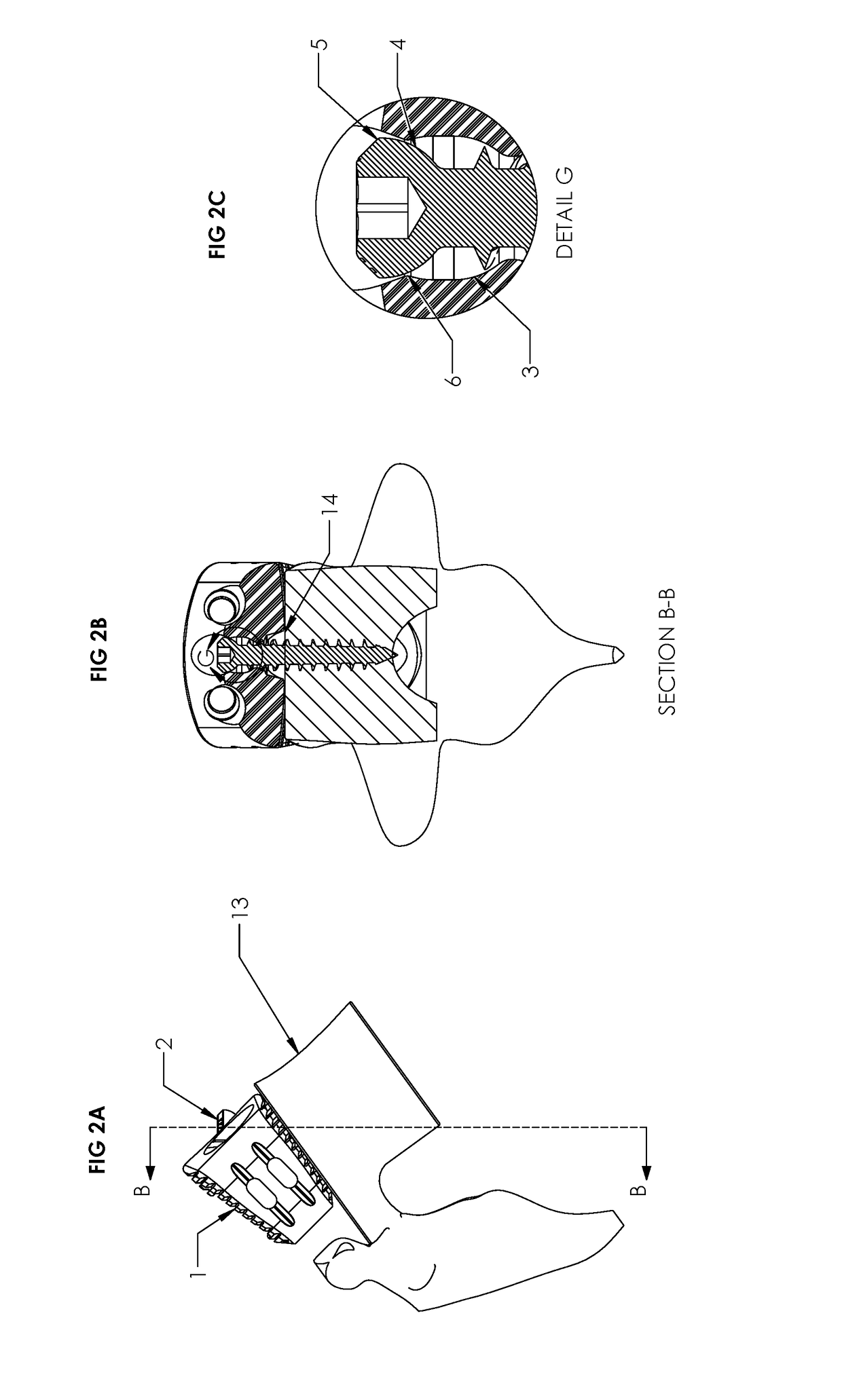
[0028]Referring to FIGS. 2A, B & C, as the bone screw 2 is being threaded into the vertebral end plate 14, its hemispherical head 4 will come in contact with the smaller diameter region 6 of the implant bone screw aperture 11. Referring to FIGS. 3A, B & C, during the bone screw 2 placement portion ...


PUM


Abstract

The presented device is an orthopedic spinal cage that is inserted from an anteriorly aspect into a patient's intervertebral disc space. The device includes a cage to maintain vertebral separation and allow for fusion. Threaded screws allow for a matting and lag feature to prevent screw back out, provide a tactile event once fully inserted, and then to provide a stepped feature for reliable screw removal with minimal axial force. These features may be adapted to any orthopedic or other application requiring the thread screw features.

Description

CROSS REFERENCE[0001]Provisional Application No.: 62 / 327,950[0002]Provisional Application Filling Date: 26 Apr. 2016[0003]Confirmation No. 9955STATEMENT OF FEDERALLY SPONSORED RESEARCH OR DEVELOPMENT[0004]This application and device have received no federally sponsored research or development assistance.BACKGROUND[0005]U.S. Classification A61F2 / 44, Joints for the spine, e.g. vertebrae, spinal discs[0006]The natural intervertebral disc contains a jelly-like nucleus pulposus surrounded by a fibrous annulus fibrosus. Under an axial load, the nucleus pulposus compresses and radially transfers that load to the annulus fibrosus. The laminated nature of the annulus fibrosus provides it with a high tensile strength and so allows it to expand radially in response to this transferred load.[0007]In a healthy intervertebral disc, cells within the nucleus pulposus produce an extracellular matrix (ECM) containing a high percentage of proteoglycans. These proteoglycans contain sulfated functional ...

Claims


Application Information

Patent Timeline
IPC IPC(8): A61B17/80A61B17/86
CPCA61B17/8057A61B2017/00946A61B17/86A61F2/4455A61F2/4465A61F2002/30782A61F2002/30787A61F2002/3079
Inventor CORDARO, NICHOLAS MICHAELCOMPTON, ROBERT
Owner ADDITIVE INNOVATIONS
Why Eureka
Eureka Blog
Learn More