Eureka AIR delivers breakthrough ideas for toughest innovation challenges, trusted by R&D personnel around the world.

Perpendicular magnetic recording medium

Active Publication Date: 2016-10-06
FUJI ELECTRIC CO LTD
View PDF5 Cites 3 Cited by
  • Summary
  • Abstract
  • Description
  • Claims
  • Application Information

AI Technical Summary

Benefits of technology

The patent describes a way to make a magnetic recording medium with a thick layer that has separate magnetic crystal grains, which is important for energy-assisted magnetic recording. This results in a more robust medium that can be used in energy-assisted magnetic recording systems.

Problems solved by technology

On the other hand, reduction in the grain diameter of the magnetic crystal grains leads to a decrease in thermal stability of the recorded magnetization (signals).
However, when the magnetic crystal grains are formed of the ordered alloy, there is involved a difficulty in forming magnetic crystal grains with uniform properties.
It is known that a difficulty is involved in forming a magnetic film having an ordered structure such as L10 type in high quality, and irregular growth of crystals is likely to occur during the film formation.

Method used


Image

  • Perpendicular magnetic recording medium
  • Perpendicular magnetic recording medium
  • Perpendicular magnetic recording medium

Examples


example 1

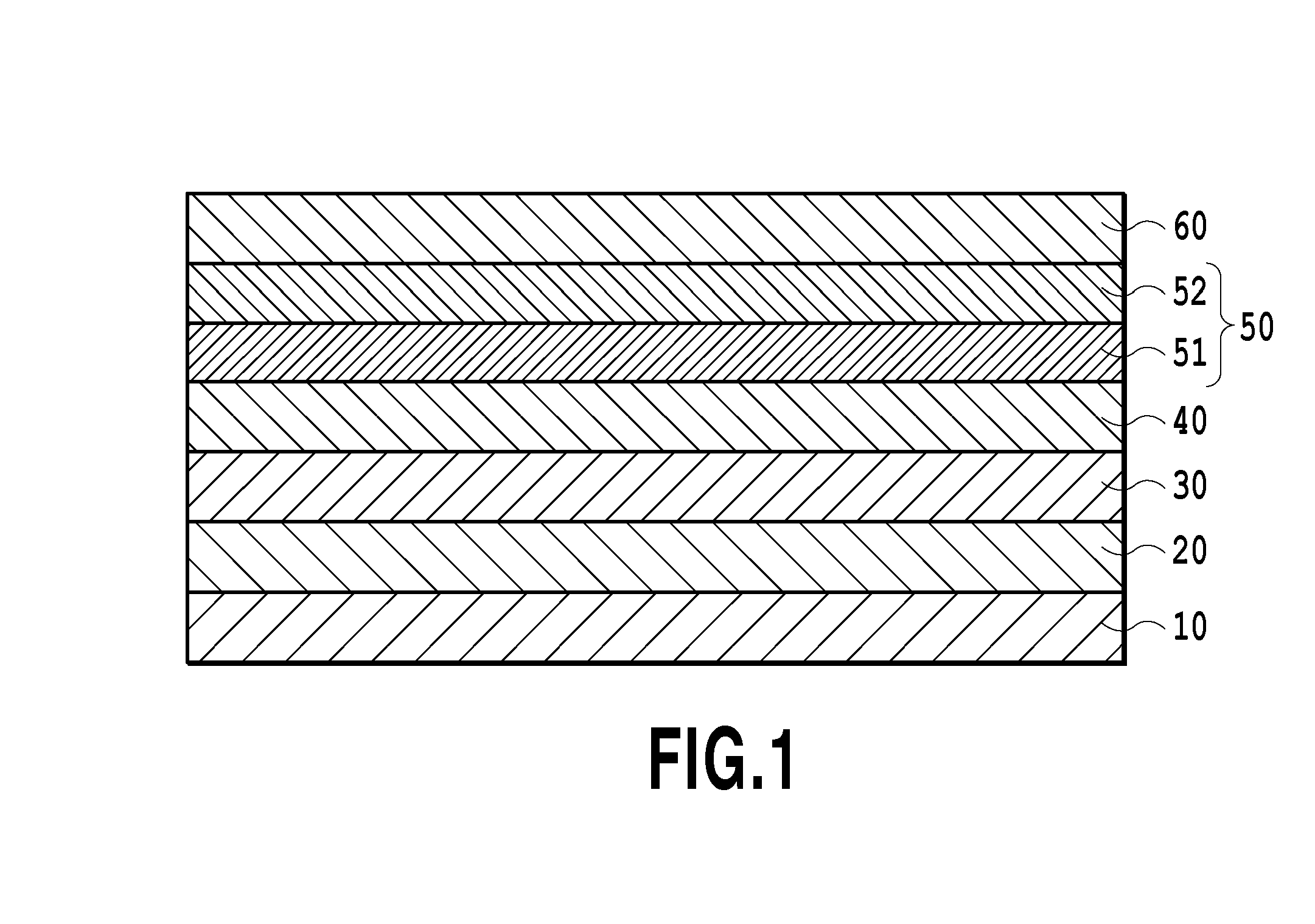
[0081]A chemically strengthened glass substrate having a flat surface (N-10 glass substrate manufactured by HOYA CORPORATION) was washed to prepare non-magnetic substrate 10. The washed non-magnetic substrate 10 was brought into a sputtering device. Then, Ta adhesive layer 20 having a thickness of 5 nm was formed by a DC magnetron sputtering method using a pure Ta target in Ar gas at a pressure of 0.3 Pa.

[0082]Next, Cr interlayer 30 having a thickness of 20 nm was formed by a DC magnetron sputtering method using a pure Cr target in Ar gas at a pressure of 0.3 Pa.

[0083]Next, the substrate was heated to a temperature of 300° C., and then MgO seed layer 40 having a thickness of 5 nm was formed by an RF sputtering method using an MgO target in Ar gas at a pressure of 0.18 Pa. The applied RF power was 100 W.

[0084]Next, the stacked body in which the seed layer 40 had been formed was heated to a temperature of 450° C., and then FePt—C first magnetic recording layer 51 having a thickness of...

example 2

[0099]A magnetic recording medium was obtained by repeating the procedure of Example 1, except for the following differences.

(a) The stacked body in which the adhesive layer 20 had been formed was heated to a temperature of 400° C., and then an MgO intermediate layer having a thickness of 1 nm was formed by an RF sputtering method using an MgO target in Ar gas at a pressure of 0.1 Pa. The applied RF power was 100 W. The Cr interlayer 30 was formed onto the MgO intermediate layer.

(b) The composition of the second magnetic recording layer 52 was changed to 75% by volume of Fe50Pt50 and 25% by volume of ZnO. The thickness of the second magnetic recording layer 52 was changed to 3 nm.

(c) The protective layer 60 was changed to a stacked structure of a Pt layer having a thickness of 5 nm and a Ta layer having a thickness of 5 nm. The Ta layer was formed by a DC magnetron sputtering method using a pure Ta target in Ar gas at a pressure of 0.3 Pa.

[0100]The magnetic recording medium of this ...

example 3

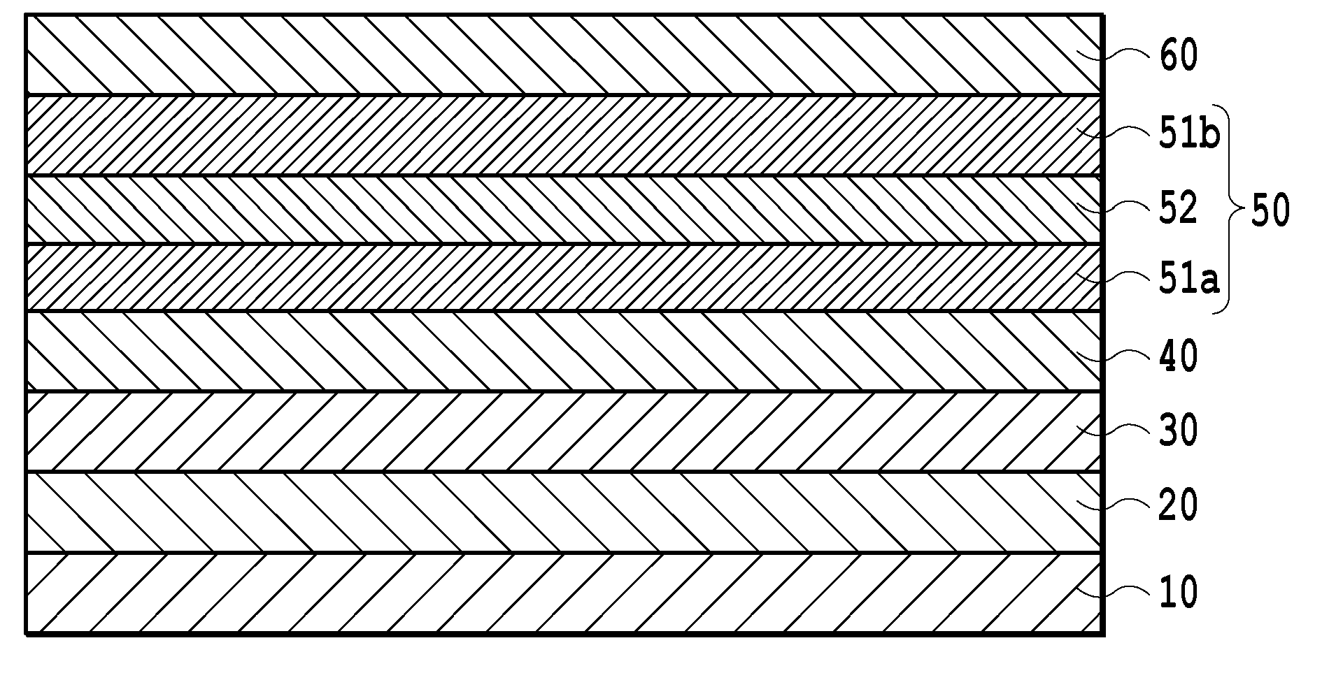
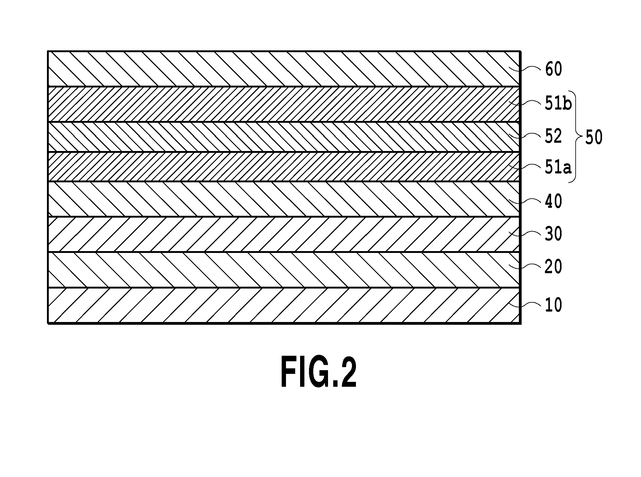
[0107]Layers up to the MgO seed layer 40 were formed in accordance with the same procedure as Example 1.

[0108]Next, the stacked body in which the seed layer 40 had been formed was heated to a temperature of 450° C., and then first FePt—C first magnetic recording layer 51a having a thickness of 2 nm was formed by a DC magnetron sputtering method using a target containing Fe50Pt50 and C in Ar gas at a pressure of 1.5 Pa. Here, the composition of the Fe50Pt50—C target was adjusted such that the obtained first magnetic recording layer 51a had a composition of 60% by volume of Fe50Pt50 and 40% by volume of C. The applied DC power was 40 W.

[0109]Next, FePt—ZnO second magnetic recording layer 52 having a thickness of 1 nm was formed by a DC magnetron sputtering method using a target containing Fe50Pt50 and ZnO in Ar gas at a pressure of 1.5 Pa, in the state that the stacked body was heated at a temperature of 450° C. Here, the composition of the Fe50Pt50—ZnO target was adjusted such that t...


PUM


Abstract

A magnetic recording medium including a magnetic recording layer of a granular structure and having a large thickness as well as excellent magnetic properties is provided. The perpendicular magnetic recording medium includes a non-magnetic substrate and a magnetic recording layer, wherein the magnetic recording layer includes first magnetic recording layers on the side of the non-magnetic substrate and second magnetic recording layers, the first magnetic layers have a granular structure including first magnetic crystal grains containing an ordered alloy and a first non-magnetic segregant surrounding the first magnetic crystal grains and containing carbon; and the second magnetic layers have a granular structure including second magnetic crystal grains containing an ordered alloy and a second non-magnetic segregant surrounding the second magnetic crystal grains and containing Zn and O.

Description

TECHNICAL FIELD[0001]The present invention relates to a perpendicular magnetic recording medium. In particular, the present invention relates to a perpendicular magnetic recording medium used in an energy-assisted magnetic recording system.BACKGROUND ART[0002]Perpendicular magnetic recording system is adopted as a technique for increasing the magnetic recording density. A perpendicular magnetic recording medium at least comprises a non-magnetic substrate, and a magnetic recording layer formed of a hard-magnetic material. Optionally, the perpendicular magnetic recording medium may further comprise: a soft-magnetic under layer formed of a soft magnetic material and playing a role in concentrating the magnetic flux generated by a magnetic head onto the magnetic recording layer; an interlayer for orienting the hard-magnetic material in the magnetic recording layer in an intended direction; a protective film for protecting the surface of the magnetic recording layer; and the like.[0003]J...

Claims


Application Information

Patent Timeline
IPC IPC(8): G11B5/82G11B5/65G11B5/667
CPCG11B5/82G11B5/656G11B5/653G11B5/667G11B5/672
Inventor UCHIDA, SHINJISHIMATSU, TAKEHITO
Owner FUJI ELECTRIC CO LTD
Why Eureka
Eureka Blog
Learn More