Vehicle and method for filling fuel gas

a fuel gas and tank technology, applied in the direction of container filling under pressure, electrochemical generators, discharging methods, etc., can solve the problems of increasing power consumption relating to heating and actual filling amount, and achieve the effect of suppressing the increase in power consumption and reducing the amount of fuel gas in the tank

Active Publication Date: 2018-09-20
TOYOTA JIDOSHA KK
View PDF25 Cites 11 Cited by
  • Summary
  • Abstract
  • Description
  • Claims
  • Application Information

AI Technical Summary

Benefits of technology

[0013]It becomes possible to provide a vehicle and a method for filling fuel gas that suppress decrease in the amount of fuel gas filled in a tan

Problems solved by technology

As a result, an actual filling amount may decrease.
Powe

Method used


Image

  • Vehicle and method for filling fuel gas
  • Vehicle and method for filling fuel gas
  • Vehicle and method for filling fuel gas

Examples


Embodiment Construction

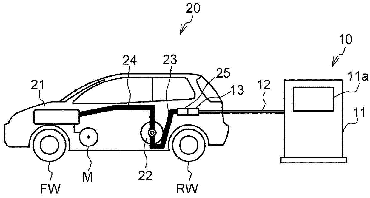
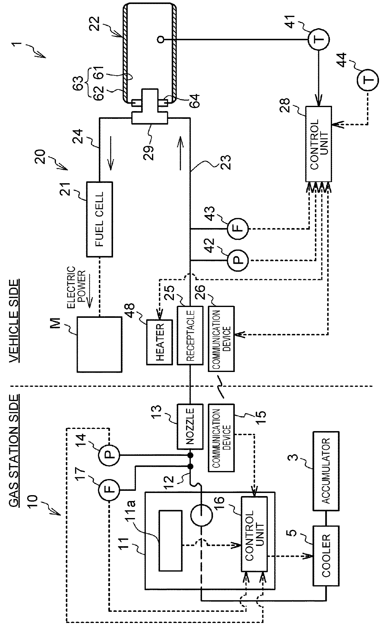
[0024]FIG. 1 is an explanatory view of a gas filling system 1. The gas filling system 1 includes a vehicle 20 that travels with electric power generated by a fuel cell 21 with use of fuel gas, and a gas station 10 that fills a tank 22 of the vehicle 20 with the fuel gas. As the fuel gas, hydrogen gas is used. FIG. 2 is an explanatory view of the gas station 10 and the vehicle 20.

[0025]First, the gas station 10 will be described. The gas station 10 includes an accumulator 3, a cooler 5, a dispenser 11, a filling hose 12, a nozzle 13, a pressure sensor 14, a communication device 15, a control unit 16, and a flow sensor 17. The accumulator 3 accumulates hydrogen gas from a hydrogen curdle which is not illustrated. The pressure of the hydrogen gas is stepped up to a specified pressure by a compressor. The cooler 5 performs preliminary cooling of the hydrogen gas coming from the accumulator 3. The dispenser 11 sends out the hydrogen gas coming from the cooler 5 to the filling hose 12 con...


PUM


Abstract

A vehicle including: a tank configured to be filled with fuel gas; a receptacle configured to be connected to a nozzle included in a fuel gas filling apparatus; a filling passage configured to provide communication between the receptacle and the tank; a heating unit configured to heat the receptacle; a determination unit configured to determine whether or not a parameter value, correlated with a filling speed of the fuel gas filled into the tank from the fuel gas filling apparatus, indicates decrease in the filling speed during filling of the fuel gas into the tank; and a control unit configured to, when the determination unit determines that the parameter value indicates decrease in the filling speed during filling of the fuel gas into the tank, to cause the heating unit to start heating of the receptacle during filling of the fuel gas into the tank.

Description

INCORPORATION BY REFERENCE[0001]The disclosure of Japanese Patent Application No. 2017-050502 filed on Mar. 15, 2017 including the specification, drawings and abstract is incorporated herein by reference in its entirety.BACKGROUND1. Technical Field[0002]The present disclosure relates to a vehicle and a method for filling fuel gas.2. Description of Related Art[0003]When a tank of a vehicle is filled with fuel gas from a fuel gas filling apparatus, a nozzle of the fuel gas filling apparatus is connected to a receptacle on the vehicle side. In order to suppress difficulty of disconnecting the nozzle and the receptacle caused by freezing, Japanese Patent Application Publication No. 2011-047491 discloses a technique of heating the receptacle when the temperature of the receptacle during filling of the fuel gas is equal to or below a specified temperature.SUMMARY[0004]When heating of the receptacle is started with reference to only the temperature of the receptacle as in JP 2011-047491 A,...

Claims


Application Information

Patent Timeline
IPC IPC(8): F17C13/10F17C5/06F17C5/04F17C13/02H01M8/04082
CPCF17C13/10F17C5/06F17C5/04F17C13/025F17C13/026H01M8/04201F17C2221/012F17C2221/035F17C2221/033F17C2260/02F17C2265/065F17C2270/0178F17C2270/0184H01M2250/20F17C5/007F17C2205/0376F17C2223/0123F17C2223/036F17C2227/0304F17C2227/0337F17C2227/0388F17C2227/039F17C2250/032F17C2250/034F17C2250/043F17C2250/0439F17C2250/0443F17C2250/0636F17C2250/075F17C2260/032F17C2270/0139F17C2270/0168Y02E60/32Y02T90/40Y02E60/50
Inventor FUJITA, KEISUKE
Owner TOYOTA JIDOSHA KK
Why Eureka
Try Eureka