
Accommodating intraocular lens device

a technology of intraocular lens and lens body, which is applied in the field of accommodating intraocular lens body, can solve the problems of inability to correct presbyopia and reading glasses, unmet needs for effective surgical intervention to correct presbyopia, and inability to adjust, so as to reduce the thickness of at least one region, and facilitate the adjustment of the lens body

Active Publication Date: 2018-09-27
LENSGEN INC
View PDF0 Cites 30 Cited by
  • Summary
  • Abstract
  • Description
  • Claims
  • Application Information

AI Technical Summary

Benefits of technology

The patent describes a toric base assembly for an accommodating intraocular lens device. This assembly can be used in a two-part device that includes a power lens. The toric base assembly provides an asymotic translation of a radially compressive force onto the power lens. The assembly has a base lens and a surrounding circular haptic with greater flexibility than other regions. This flexibility can result in a toric power change in the base lens or power lens. The patent suggests options to increase the flexibility, such as reducing the thickness of the haptic or adding shaped cut-outs. These technical effects can improve the performance and efficiency of the accommodating intraocular lens device.

Problems solved by technology

As conventional IOL devices are primarily focused for distance visions, they fail to correct for presbyopia and reading glasses are still required.
Thus, while patients who undergo a standard IOL implantation no longer experience clouding from cataracts, they are unable to accommodate, or change focus from near to far, from far to near, and to distances in between.
Despite the success of LASIK in treating myopia, there remains an unmet need for an effective surgical intervention to correct for presbyopia, which cannot be treated by conventional LASIK procedures.
While there is a general acceptance among physicians and patients of having implantable intraocular lens in the treatment of cataracts, similar procedures to correct for presbyopia represent only 5% of the U.S. cataract market.

Method used


Image

  • Accommodating intraocular lens device
  • Accommodating intraocular lens device
  • Accommodating intraocular lens device

Examples


Embodiment Construction

[0107]Specific, non-limiting embodiments of the present invention will now be described with reference to the drawings. It should be understood that such embodiments are by way of example and are merely illustrative of but a small number of embodiments within the scope of the present invention. Various changes and modifications obvious to one skilled in the art to which the present invention pertains are deemed to be within the spirit, scope and contemplation of the present invention.

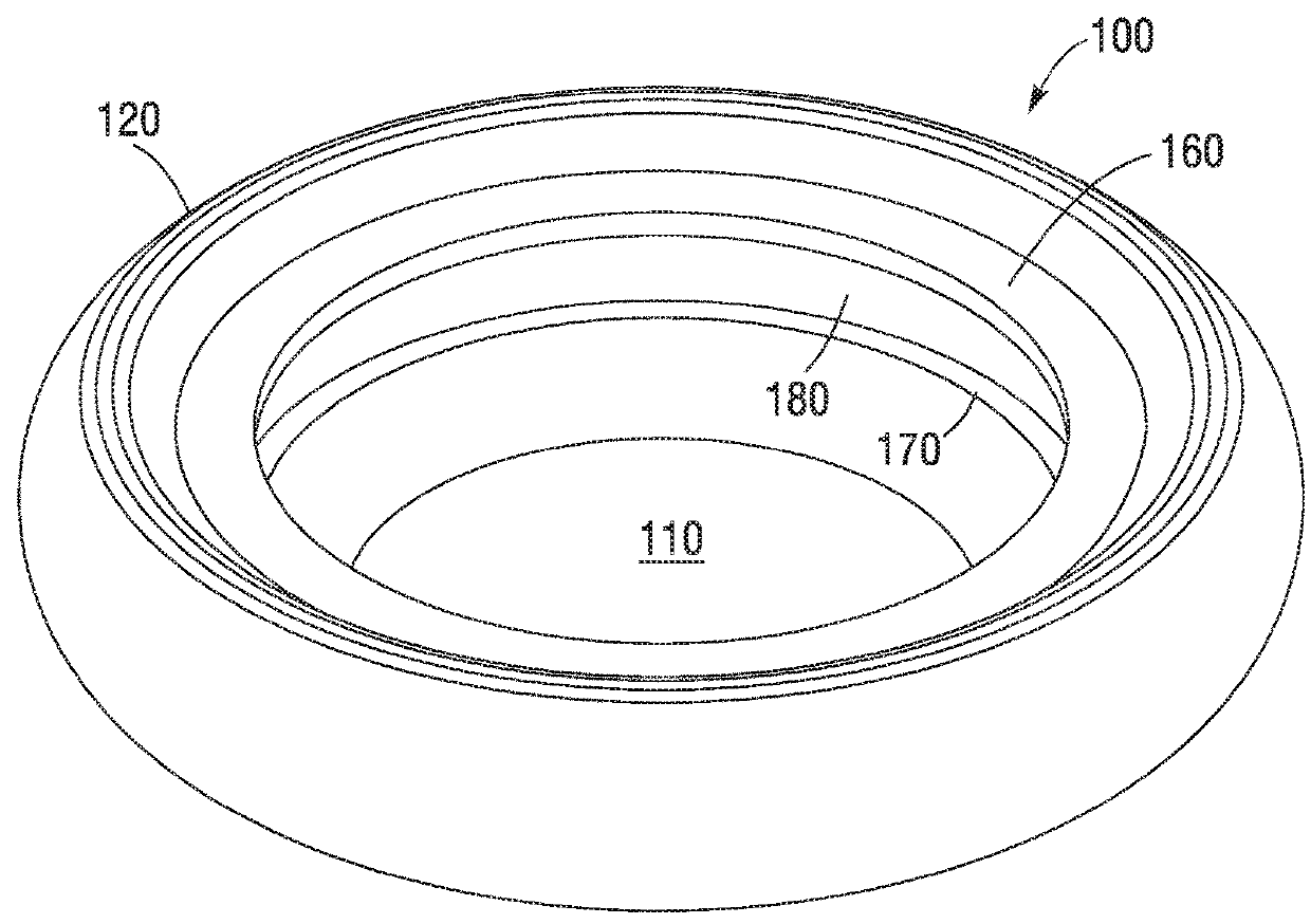
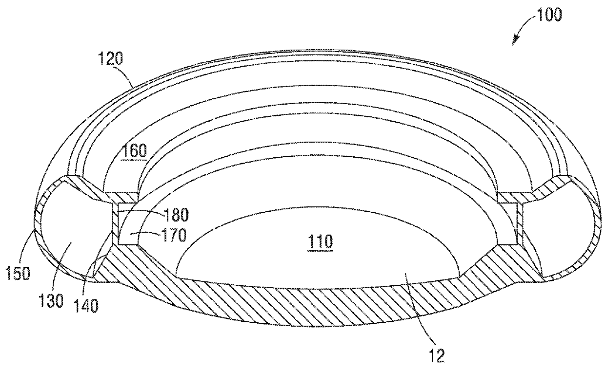
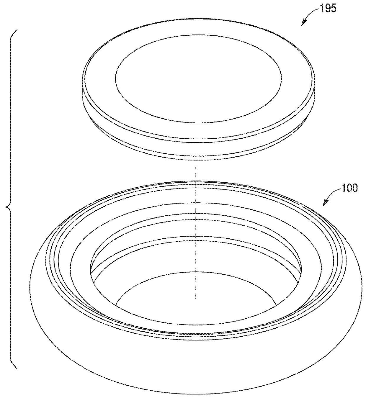
[0108]Various embodiments of accommodating intraocular lenses (IOL) described herein and may comprise the power changing feature of a power lens in connection with a base lens. In one optional embodiment, the power changing feature of the IOL is driven by fluid optics within a closed volume of a power lens that comprises a flexible membrane and a lens or optic. One significant advantage of this embodiment is that the closed volume of the power lens that spaces apart the flexible membrane and the lens ma...


PUM


Abstract

An accommodating intraocular lens device is provided. The accommodating intraocular lens device comprises a base assembly and a power lens. The base assembly comprises a first open end, a second end coupled to a base lens, and a haptic surrounding a central cavity. The haptic may comprise an outer periphery, an inner surface and a height between a first edge and a second edge. The power lens is configured to fit within the central cavity. The power lens may comprise a first side, a second side, a peripheral edge coupling the first and second sides, and a closed cavity configured to house a fluid. The first side of the power lens may be positioned at a predetermined distance from the first edge of the haptic.

Description

CROSS-REFERENCE TO RELATED APPLICATIONS[0001]The present application is a continuation of International Patent Application No. PCT / US2016 / 064491, filed on Dec. 1, 2016, which in turn claims the benefit of U.S. Provisional Application No. 62 / 261,790, filed Dec. 1, 2015, the contents of which are incorporated herein by reference in their entireties into the present disclosure.FIELD OF THE INVENTION[0002]The invention relates generally to an accommodating intraocular lens device and, more particularly, to an accommodating intraocular lens device configured for implantation in a lens capsule or sulcus of a subject's eye.BACKGROUND[0003]Surgical procedures on the eye have been on the rise as technological advances permit for sophisticated interventions to address a wide variety of ophthalmic conditions. Patient acceptance has increased over the last twenty years as such procedures have proven to be generally safe and to produce results that significantly improve patient quality of life.[...

Claims


Application Information

Patent Timeline
IPC IPC(8): A61F2/16A61F9/007
CPCA61F2/16A61F9/00736A61F2002/1681B29D11/026B29D11/02A61F2/1648G02C7/08A61F2/1624G02C7/04A61F2002/1682A61F2220/0033G02B3/14A61F2002/169
Inventor BRADY, DANIELSILVESTRINI, THOMASRAO, RAMGOPAL
Owner LENSGEN INC
Features
  • Generate Ideas
  • Intellectual Property
  • Life Sciences
  • Materials
  • Tech Scout
  • Unparalleled Data Quality
  • Higher Quality Content
  • 60% Fewer Hallucinations
Learn More