Method and apparatus for fabrication of lattice composite fuselage for commercial aircraft employing steered fiber lay up

a composite fuselage and steered fiber technology, applied in the direction of power plant exhaust arrangement, transportation and packaging, other domestic articles, etc., can solve the problems of non-recurring and recurring expenses, increased weight and cost, and less uniform lattice in aircraft structures

Inactive Publication Date: 2018-09-27
THE BOEING CO
View PDF3 Cites 1 Cited by
  • Summary
  • Abstract
  • Description
  • Claims
  • Application Information

AI Technical Summary

Benefits of technology

[0006]Exemplary embodiments provide a method for fabrication of an aerospace structure. At least one unidirectional Steered Fiber Lay-up (SFL) head is employed to lay down a plurality of collimated tows in a predetermined laminated pattern on a mold surface to produce a fuselage skin. At least one cross plied laminate SFL head is then employed to lay down a cross plied laminate base interface on the fuselage skin to establish a lattice rib shape for each of a plurality of lattice ribs. A band placement head in the cross plied laminate SFL head is steered to avoid structural design features and to maintain spacing from adjacent steered lattice ribs. The unidirectional SFL head is then em...

Problems solved by technology

Furthermore, existing designs are based on the concept of orthotropic material which does not take full advantage of the available anisotropic properties of modern composite unidirectional materials.
This results in excessive weight and cost, in growth of both Non-Recurring and Recurring Expenses (NRE, RE) in the course of manufacturing of composite fuselages.
However, a uniform Lattice is less efficient in aircraft structures like fuselage sections which incorporate do...

Method used


Image

  • Method and apparatus for fabrication of lattice composite fuselage for commercial aircraft employing steered fiber lay up
  • Method and apparatus for fabrication of lattice composite fuselage for commercial aircraft employing steered fiber lay up
  • Method and apparatus for fabrication of lattice composite fuselage for commercial aircraft employing steered fiber lay up

Examples


Embodiment Construction

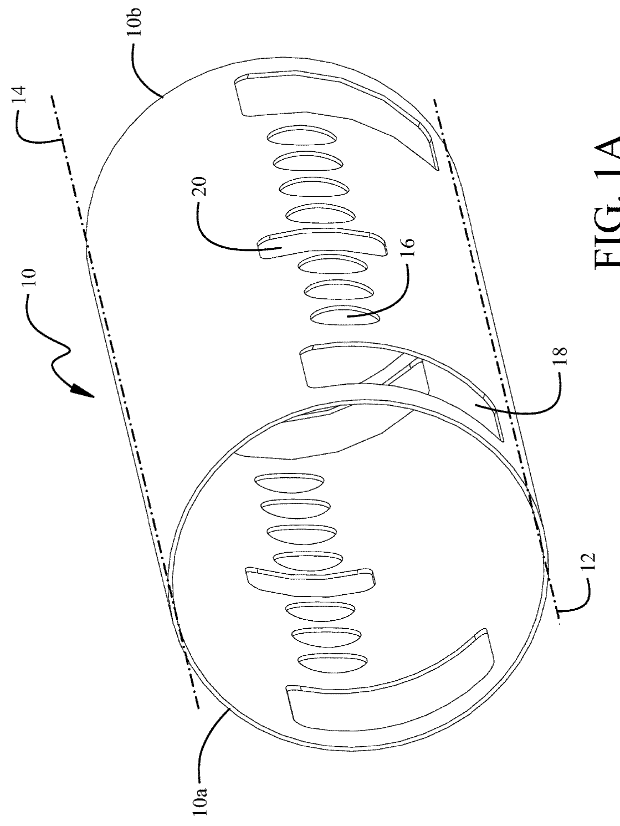
[0019]The embodiments and methods described herein provide combined use of automated Steered Fiber Lay-up (SFL) and lattice design to fabricate integrally stiffened, stringerless sections of composite fuselage which incorporate windows, doors and other design features. The fuselage skin and stiffening lattice are fabricated as integral structure on the surface of a mold employing an automatic layup machine. This approach eliminates the need to separately produce skin, stringers and frames by different manufacturing equipment and a final assembly using co-curing, co-bonding, fastening. Use of automated SFL allows variation in lattice geometry and rib shape to accommodate local design features or disruptions. Unlike WFW no manual layup is required to support local reinforcement in areas of features or disruptions such as fuselage openings.

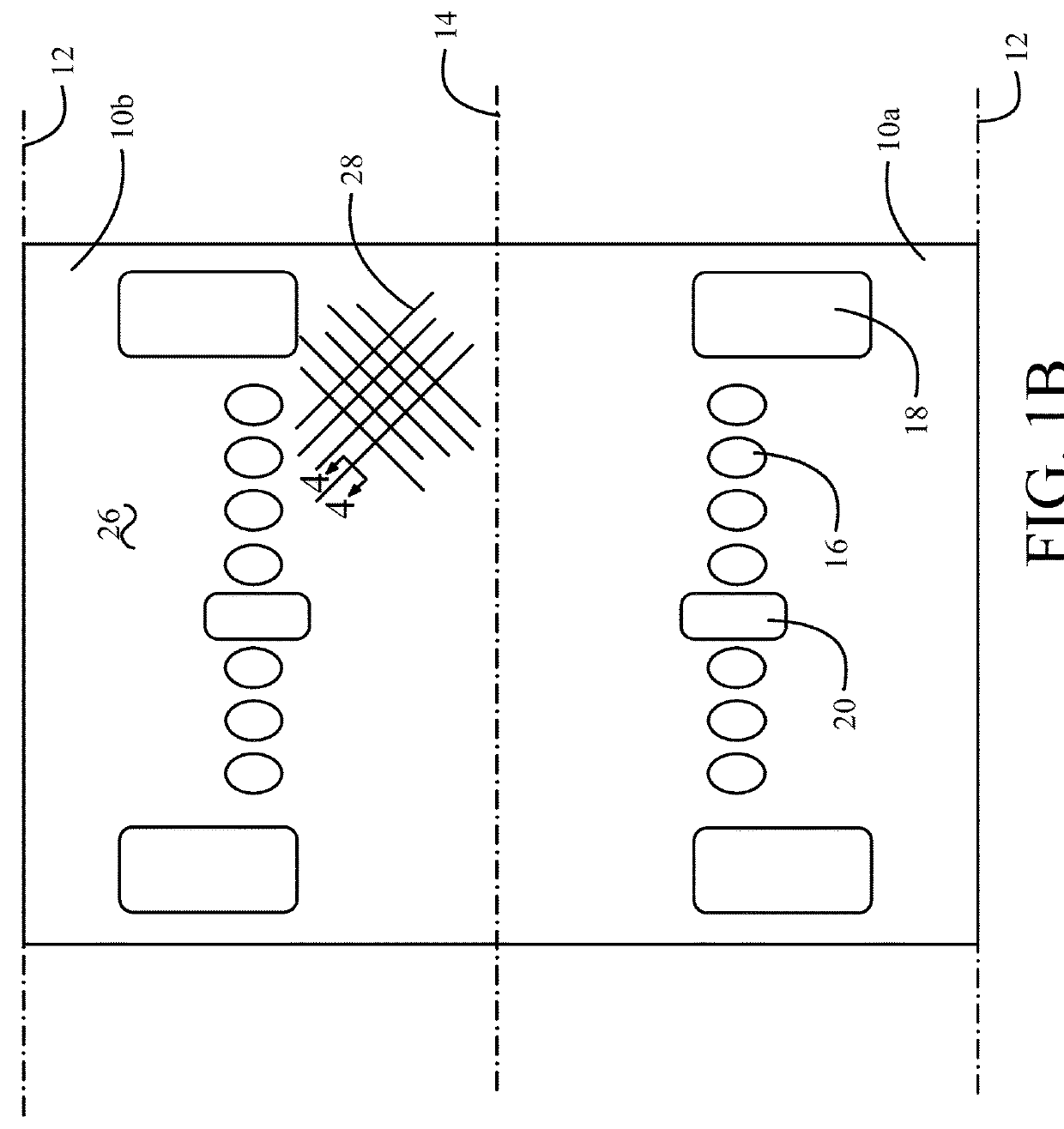
[0020]Referring to the drawings, FIG. 1A shows an exemplary fuselage section 10 for a commercial aircraft and FIG. 1B shows the fuselage depicted in...


PUM

PropertyMeasurementUnit
Shapeaaaaaaaaaa
Widthaaaaaaaaaa
Tensionaaaaaaaaaa

Abstract

A system for fabrication of an aerospace structure incorporates a mold having a surface and at least one unidirectional SFL head adapted to lay down a plurality of collimated tows in a predetermined laminated pattern on the mold surface to produce a fuselage skin. At least one cross plied laminate SFL head is adapted to lay down a cross plied laminate base interface on the fuselage skin to establish a lattice rib shape for each of a plurality of lattice ribs. The cross plied laminate SFL head has a band placement head steerable to avoid structural design features and to maintain spacing from adjacent steered lattice ribs. The unidirectional SFL head is further adapted to lay down a plurality of collimated tows on the base interface of each of the plurality of lattice ribs for a first plurality of unidirectional tow plies in each lattice rib. The unidirectional SFL head has a fiber placement head steerable to match the lattice rib shape to avoid structural design features and to maintain spacing from adjacent steered lattice ribs.

Description

BACKGROUND INFORMATIONField[0001]Embodiments of the disclosure relate generally to fabrication of composite structures for aircraft and more particularly to fabrication of aircraft fuselages having a modified lattice structure for carrying structural loads created with steered fiber layup using two or more heads for fiber placement with unidirectional tows and cross plied laminates providing high damage tolerance.Background[0002]Composite fuselages employed in existing commercial aircraft use composite skin supported by separately fabricated stiffening elements. Frames and stringers carry the substantial operational loads and are added to the composite skin after fabrication similar to metallic structural assembly approaches (a.k.a. “Black Aluminum” design). Skin, Frames and Stringers are typically fabricated based on different manufacturing technologies which require different manufacturing equipment, transportation of fuselage components from different production sites to the fina...

Claims


Application Information

Patent Timeline
IPC IPC(8): B64F5/10B29C70/38B64C1/06
CPCB64F5/10B29C70/382B64C2001/0072B29L2031/3082B64C1/068B64C1/12B64C3/187B64D33/04B29C70/38B29D99/0014B64C1/08Y02T50/40B29C70/384
Inventor SOKOLOV, BORIS B.RASSAIAN, MOSTAFAPIEHL, MARC J.
Owner THE BOEING CO
Why Eureka
Try Eureka