Mitigation of interplay effect in particle radiation therapy

a particle radiation therapy and interplay technology, applied in radiation therapy, x-ray/gamma-ray/particle-irradiation therapy, therapy, etc., can solve the problem of severe local underdosage and/or overdosage inside the treatment target volume, and the interplay effect is more serious, so as to reduce the interplay effect.

Active Publication Date: 2018-10-04
UNIV OF MARYLAND +1
View PDF0 Cites 2 Cited by
  • Summary
  • Abstract
  • Description
  • Claims
  • Application Information

AI Technical Summary

Benefits of technology

[0009]Accordingly, the interplay effect in each individual layer (or energy layer) may be smeared out by tuning a duration of layer treatment delivery to one or more periods of movement. Further, the dose delivered to each spot in the layer may be delivered in equal portions with equal temporal separations over duration of the period of movement. This ensures that the mean shift of each spot relative to its planned position is close to zero, which in turn gives a large reduction of the interplay effect. Also, it possible to use a different number of repaintings for each spot, but still spread out the spot repaintings throughout the period of movement.
[0010]Therefore, the new scan technique spreads the treatment delivery of each energy layer over the period of movement (e.g., a breathing cycle), allows spot-specific numbers of spot repaintings, and ensures that the spot repaintings are spread over the duration of the movement period. Mitigation of the interplay effect in particle radiation therapy by using the new scan technique is superior to conventional methods of mitigating the interplay effect. Moreover, the new scan technique allows safe PBS treatments of tumors undergoing respiratory motion in the thorax or abdomen, including SBRT treatments delivered in very few fractions. In an embodiment, no monitoring of the patient's breathing or synchronization of the treatment delivery to the breathing phase is needed. Further, the new scan technique may be immediately implemented at existing particle radiation therapy centers such as cyclotron-based proton radiation therapy facilities without any requirements of intra-treatment motion monitoring, gating, or synchronization between patient breathing and treatment delivery. In an embodiment, the new scan technique involves configuring the spot treatment delivery sequence in a Digital Imaging and Communications in Medicine (DICOM) proton radiation treatment plan.

Problems solved by technology

The resulting redistribution of dose in the treatment target tissue is called the interplay effect, and it can lead to severe local underdosage and / or overdosage inside the treatment target volume.
Unlike other motion-induced dose perturbations that impact the dose at the treatment target edge (e.g., dose blurring due to random position errors and dose shifts due to systematic position errors), the interplay effect typically cannot be accounted for by a simple expansion of the high-dose radiation volume with safety margins.
Although the interplay effect may tend to average out after several treatment deliveries because the hot spot and cold spot locations typically differ randomly between each treatment delivery, the interplay effect is more serious for treatments delivered in few fractions because the dose smearing effect of many fractions is absent.
Since SBRT is delivered in few fractions, SBRT is susceptible to pronounced interplay effect in moving target organs, such as lung, liver, or pancreas.
Consequently, many particle radiation therapy centers do not offer SBRT treatments at all.
Even for normal-fractionated treatments, many particle radiation therapy centers only treat highly selected tumors with minor motion due to respiratory motion.

Method used


Image

  • Mitigation of interplay effect in particle radiation therapy
  • Mitigation of interplay effect in particle radiation therapy
  • Mitigation of interplay effect in particle radiation therapy

Examples


Embodiment Construction

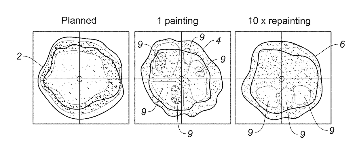
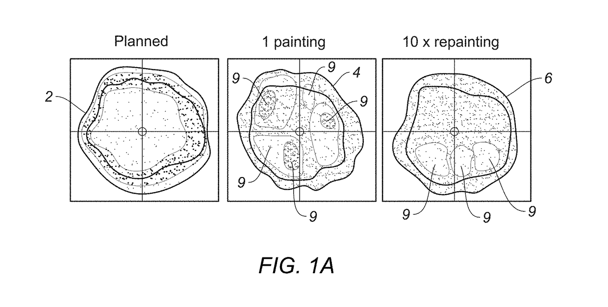
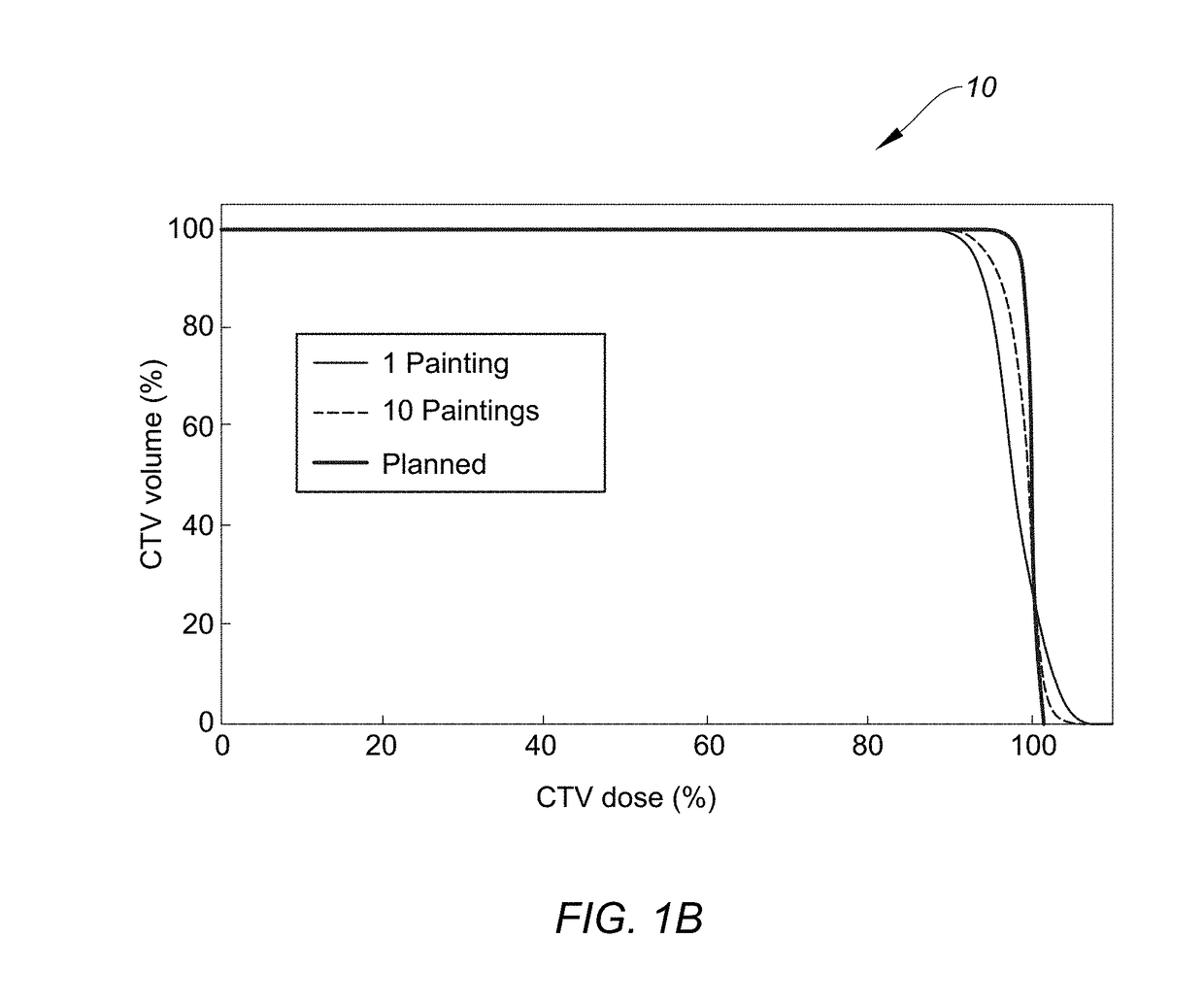
[0039]Reference will now be made in detail to embodiments, examples of which are illustrated in the accompanying drawings. While the disclosure will be described in conjunction with these embodiments, it should be understood that they are not intended to limit the disclosure to these embodiments. On the contrary, the disclosure is intended to cover alternatives, modifications and equivalents, which may be included within the spirit and scope of the disclosure as defined by the appended claims. Furthermore, in the following detailed description, numerous specific details are set forth in order to provide a thorough understanding. However, it will be recognized by one of ordinary skill in the art that embodiments may be practiced without these specific details.

[0040]Although the description will focus on proton radiation therapy and proton pencil beam scanning (PBS) therapy, the description is also applicable to particle radiation therapy that uses neutrons, ions, or electrons. The pr...


PUM


Abstract

The present disclosure relates to a new scan technique for particle radiation therapy that may be used for cancer treatment. One embodiment relates to a method of mitigating interplay effect in particle radiation therapy in a moving target including a period of movement, where the particle radiation therapy defines a planned dose in each spot of each layer of the moving target. The method comprising dividing the planned dose in each spot into a number of spot repaintings; and generating a scan pattern for each layer by defining a beam-on time at each spot for each spot repainting, and calculating a wait time between consecutive beam-on times to distribute the spot repaintings for each spot of a respective layer are distributed over a duration of an integer number of periods of movement.

Description

CROSS-REFERENCE TO RELATED APPLICATIONS[0001]This application claims the benefit of and priority to U.S. Provisional Application No. 62 / 445,008, filed on Jan. 11, 2017, which is hereby incorporated by reference in its entirety.FIELD[0002]Embodiments relate to particle radiation therapy. More specifically, embodiments relate to scan techniques to mitigate interplay effect in delivery of particle radiation to a treatment target in motion.BACKGROUND[0003]Particle radiation therapy (also called hadron therapy) is a form of external beam radiotherapy that uses beam(s) of energetic protons, ions, electrons, or electrons for treatment of cancer or other diseases. Further, pencil beam scanning (PBS) therapy is a type of particle radiation therapy that often allows excellent three-dimensional (3D) shaping of a high-dose radiation volume to a shape of a treatment target such as a tumor. With particle PBS therapy, the radiation treatment is delivered in several layers (beam energies or energy ...

Claims


Application Information

Patent Timeline
Patent Type & Authority Applications(United States)
IPC IPC(8): A61N5/10
CPCA61N5/1067A61N5/1039A61N5/1037A61N5/1044A61N5/1075A61N2005/1087A61N2005/1089A61N5/00A61N5/1043A61N5/1068
Inventor POULSEN, PER RUGAARDELEY, JOHNLANGNER, ULRICHLANGEN, KATJA
Owner UNIV OF MARYLAND
Why Eureka
Try Eureka