Systems and methods for solution coating a substrate

a technology of solution coating and substrate, applied in the direction of catalyst activation/preparation, physical/chemical process catalysts, machines/engines, etc., can solve the problem of not uniformly sucking the solution or slurry, difficult to accurately draw a low viscosity material into the substrate by an applied vacuum, and the difficulty of uniform distribution of low viscosity materials through the substra

a technology of solution coating and substrate, applied in the direction of catalyst activation/preparation, physical/chemical process catalysts, machines/engines, etc., can solve the problem of not uniformly sucking the solution or slurry, difficult to accurately draw a low viscosity material into the substrate by an applied vacuum, and the difficulty of uniform distribution of low viscosity materials through the substra

US20180281011A1Inactive Publication Date: 2018-10-04BASF CORP

Image

  • Systems and methods for solution coating a substrate
  • Systems and methods for solution coating a substrate
  • Systems and methods for solution coating a substrate

Examples


Embodiment Construction

[0120]Before describing several exemplary embodiments of the invention, it is to be understood that the invention is not limited to the details of construction or process steps set forth in the following description. The invention is capable of other embodiments and of being practiced or being carried out in various ways.

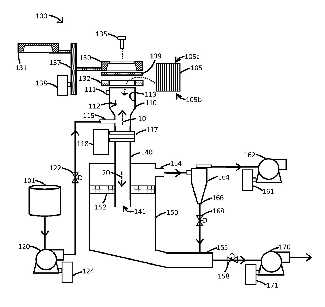
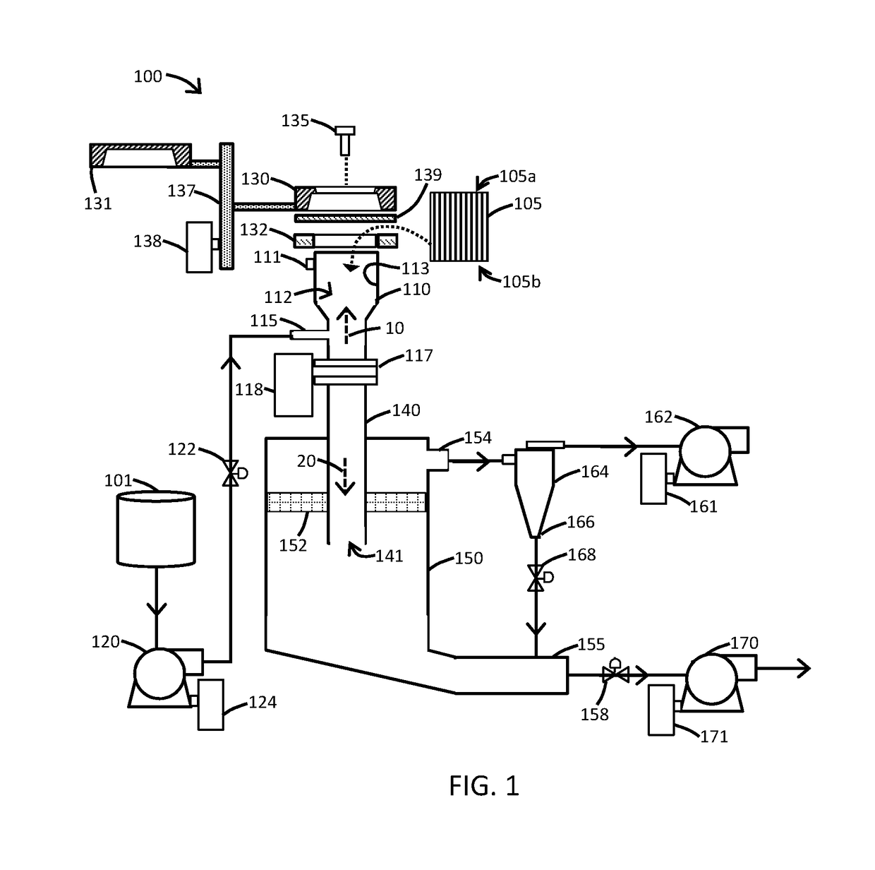
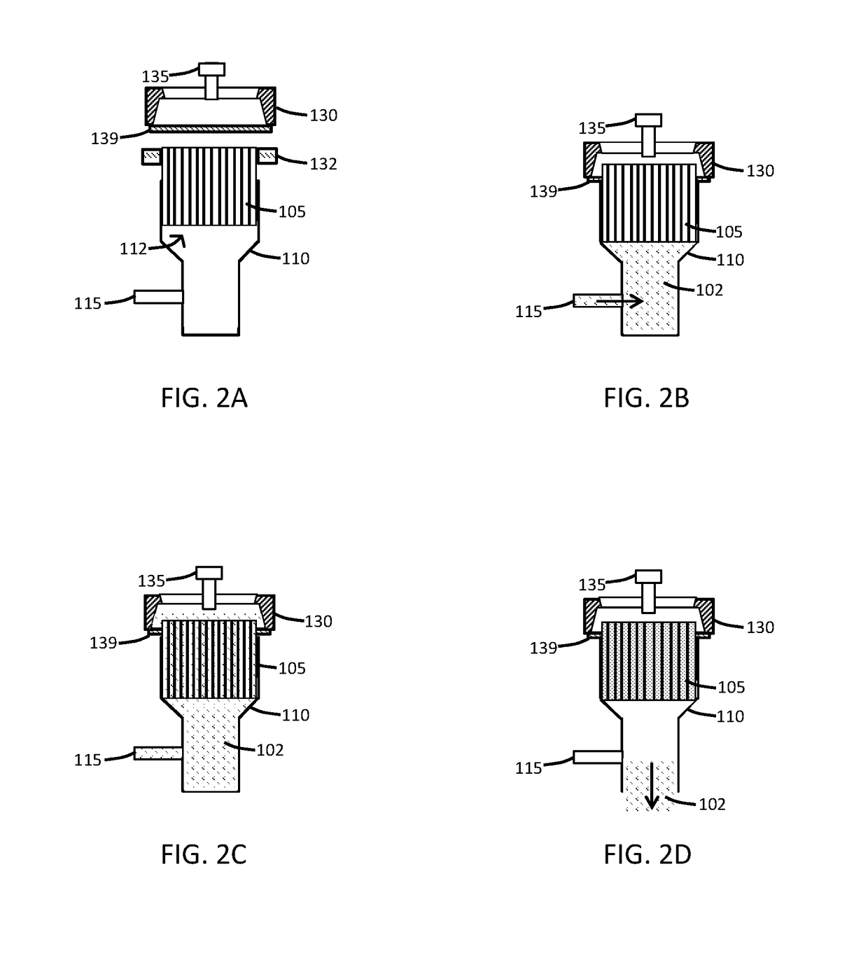
[0121]The present disclosure provides systems and methods suitable for coating a solution onto at least a portion of a substrate. In particular, a substrate having a plurality of pores and / or channels formed therein can be provided with a washcoat on the walls defining the pores and / or the channels.

[0122]In one or more embodiments, the washcoat, also referred to as a wet coating, may be formed by preparing a slurry containing a specified solids content (e.g., about 5% to about 60% by weight) of a catalyst or another material in a liquid carrier or vehicle, which is then coated onto a substrate and dried to provide a washcoat layer. As used herein, the term “washcoat...


PUM

PropertyMeasurementUnit
Timeaaaaaaaaaa
Viscosityaaaaaaaaaa
Heightaaaaaaaaaa

Abstract

Described herein is a coating system configured for providing a washcoat onto a substrate. The coating system can be configured to pump a coating solution, particularly a low viscosity solution, into a coating vessel have the substrate positioned therein. The coating system further includes elements configured for removal of a non-coating portion of the coating solution from the substrate and recycling of the non-coating portion. Also described herein are methods for applying a washcoat to a substrate as well as multi-station coater systems.

Description

FIELD OF THE DISCLOSURE[0001]The present disclosure relates to coating of a substrate, particularly a substrate comprising a plurality of pores or channels therein, with a low viscosity coating solution.BACKGROUND[0002]Catalytic converters are well known for the removal and / or conversion of the harmful components of exhaust gases. While catalytic converters have a variety of constructions for this purpose, one form of construction is a catalytically coated rigid skeletal monolithic substrate, or honeycomb-type element which has a multiplicity of longitudinal channels or cells to provide a catalytically coated body having a high surface area. The rigid, monolithic substrate can be fabricated from ceramics and other materials. Such materials and their construction are described, for example, in U.S. Pat. Nos. 3,331,787 and 3,565,830 each of which is incorporated herein by reference.[0003]A monolithic honeycomb substrate will typically have an inlet end and an outlet end, with multiple...

Claims


Application Information

Patent Timeline
04 Oct 2018
Publication
US20180281011A1
IPC
B05C3/109; B05C7/04; B05D1/18; B05D3/02; B05D7/22
CPC
B05C3/109; B05C7/04; B05D1/18; B05D3/0254; B05D7/22; F01N3/28; B01J37/0215; F01N3/2828
Inventors
GRAMICCIONI, GARY A.; PILLAI, KRISHNAN S.