Oxidation barrier coatings for silicon based ceramics

a technology of oxidation barrier coating and silicon based ceramics, which is applied in the field of coatings for ceramics, can solve the problems of siosub>2 /sub>scale, the loss of ceramic material from ceramic combustor and turbine components at a few microns per hour, and the erosion of silicon based ceramics

Active Publication Date: 2005-05-26
HONEYWELL INT INC
View PDF19 Cites 72 Cited by
  • Summary
  • Abstract
  • Description
  • Claims
  • Application Information

AI Technical Summary

Benefits of technology

[0016] In another aspect of the invention, a scandium silicate protective barrier coating for a silicon-based substrate includes the step of sintering / heat treating the silicate to densify it and bond it to the substrate in a furnace atmosphere comprised of moist hydrogen, which to avoid explosion hazards may also include an inert gas. A tantalum oxide alloy environmental barrier coating may be formed on the protective barrier coating and a stabilized zirconia thermal barrier coating may be formed on the environmental barrier coating.

Problems solved by technology

The high temperature and high pressure environment of the turbine engine as well as the high gas velocity can cause erosion of silicon based ceramics.
Evaporation of silicon hydroxide from ceramic surfaces and erosion of ceramic caused by high speed combustion gases passing over ceramic surfaces leads to the loss of ceramic material from ceramic combustor and turbine components at rates of a few microns per hour.
However, tantalum oxide permits diffusion of oxygen, resulting in the formation of a SiO2 layer below the tantalum oxide layer.
The thicker SiO2 scale was predominately crystobalite, and was excessively cracked during cooling from the operating temperature.
In addition, to compromising the adhesion of the tantalum oxide coating, the crystobalite reduced the mechanical strength of the Si3N4 substrate.
However, plasma spray does not deposit a uniform thickness coating onto complex shapes such as multi-airfoil components.
But the process disclosed by Tanaka limits the coating composition because it allows interaction of the coating with the substrate.
Thus, the manufacturing processes required to achieve the correct compositions required in Tanaka are more critical and therefore more expensive.
Thick dense coatings are well known to reduce the strength of the substrate.
In addition, thick coatings can not beneficially be applied to airfoil like applications as they add too much weight to the airfoil and, because space is limited, result in the thickness of the airfoil having to be reduced and hence its load carrying capacity.
This high sintering temperature can limit and compromise the strength properties of the substrate.
In addition, the functional cycle times and operating temperatures reported in Tanaka are inadequate to meet turbine engine requirements.
This requirement would eliminate possible unfavorable reactions between the coating and the substrate's sintering aid, but limits the range of coatings that can be used.
For example a lanthanum compound is beneficial as a sintering aid in the silicon nitride, but is detrimental in the protective coatings.

Method used


Image

  • Oxidation barrier coatings for silicon based ceramics
  • Oxidation barrier coatings for silicon based ceramics
  • Oxidation barrier coatings for silicon based ceramics

Examples


Embodiment Construction

[0025] The following detailed description is of the best currently contemplated modes of carrying out the invention. The description is not to be taken in a limiting sense, but is made merely for the purpose of illustrating the general principles of the invention, since the scope of the invention is best defined by the appended claims.

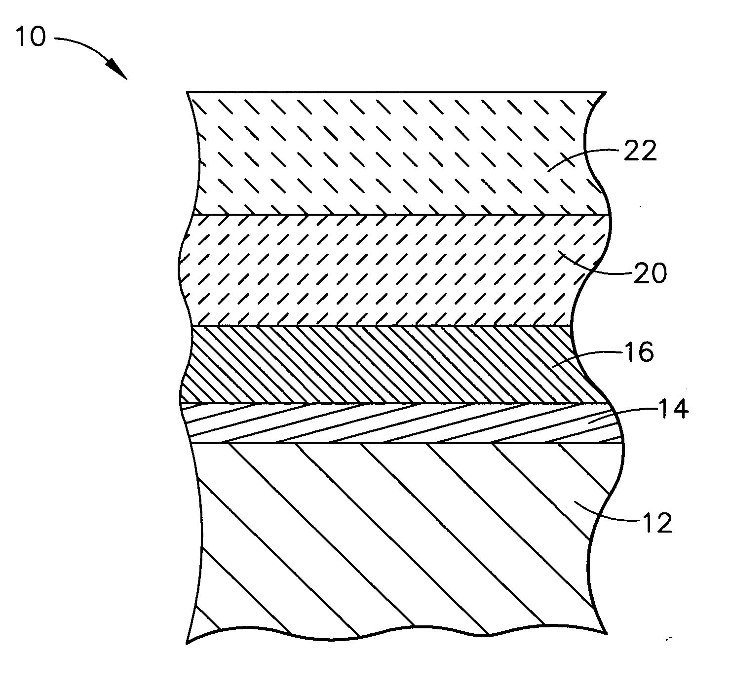
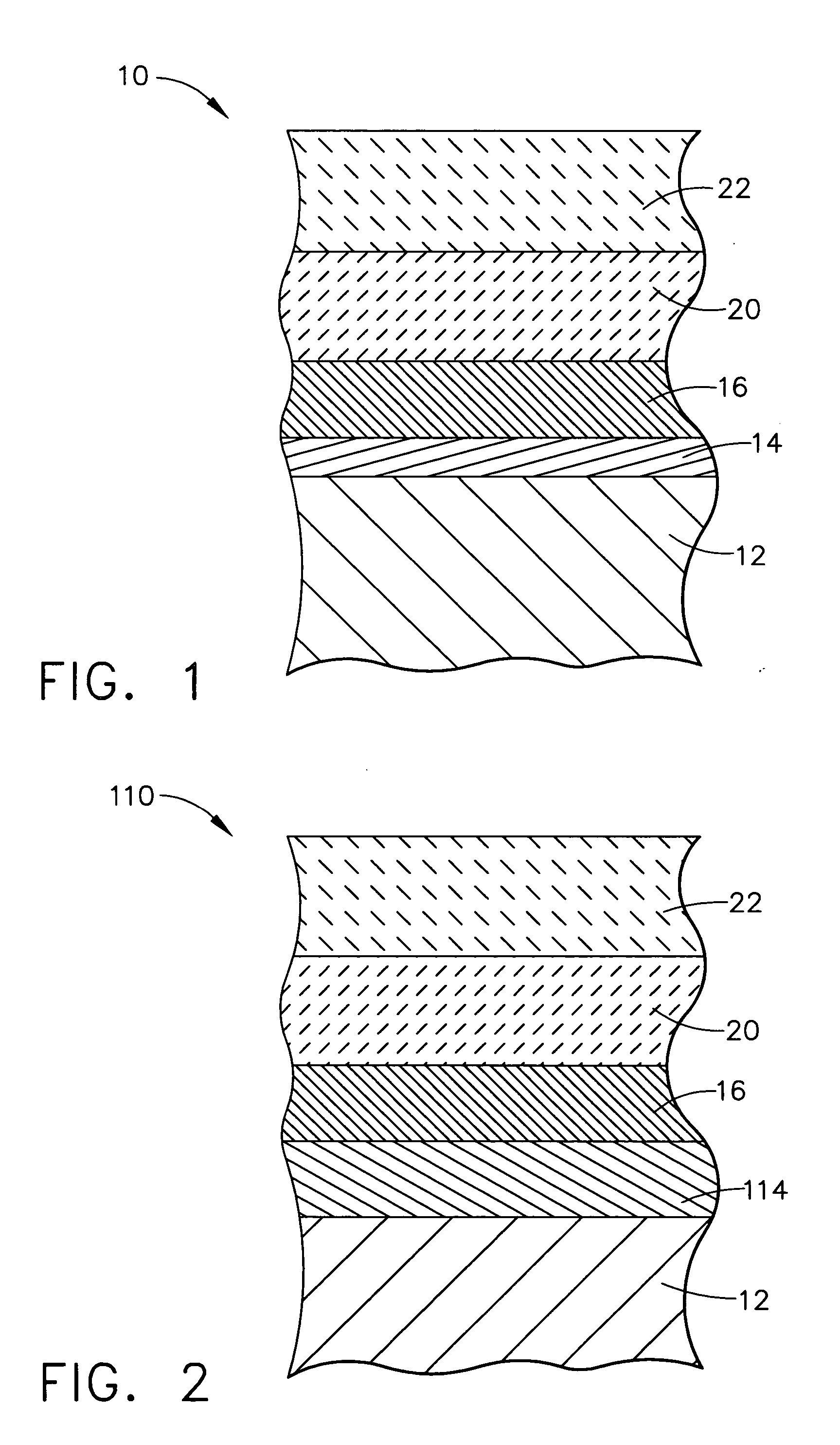
[0026] Airfoils, combustors, and turbine engine components made from silicon nitride and silicon carbide have the potential to substantially improve turbine engine performance. But these silicon-based components require barrier coatings to protect them from the turbine engine-operating environment. In general, the present invention provides a coating system that includes a cation diffusion barrier coating and an oxidation barrier coating of silicon oxynitride and metallic silicates. The diffusion barrier coating prevents undesirable diffusion of cations from the substrate into the coating system. Cations are created in the substrate during formation o...


PUM

PropertyMeasurementUnit
thicknessaaaaaaaaaa
thickaaaaaaaaaa
thickaaaaaaaaaa

Abstract

A protective barrier coating system including a diffusion barrier coating and an oxidation barrier coating and method for use in protecting silicon-based ceramic turbine engine components. A complete barrier coating system includes a thermal barrier coating of stabilized zirconia and an environmental barrier coating of an alloyed tantalum oxide. The oxidation barrier coating includes a layer of metallic silicates formed on a substrate of silicon nitride or silicon carbide to be protected. The oxidation barrier coating can include silicates of scandium, ytterbia or yttrium. The oxidation barrier coating may also include an inner layer of Si2ON2 between the diffusion barrier and the metallic silicate layer. The oxidation barrier coating can be applied to the substrate by spraying, slurry dipping and sintering, by a sol-gel process followed by sintering, by plasma spray, or by electron beam-physical vapor deposition. The diffusion layer of essentially pure Si3N4 can be applied to the substrate to prevent the migration of damaging cations from the protective layers to the substrate and is preferably formed by chemical vapor deposition. A method for protecting silicon based substrates can comprise a step of forming an oxidation barrier coating on a substrate, where a step of forming the oxidation barrier includes a step of sintering the oxidation barrier and substrate in a wet gas containing hydrogen.

Description

BACKGROUND OF THE INVENTION [0001] The present invention relates generally to coatings for ceramics, and, more particularly, to apparatus and methods to protect ceramic surfaces in high temperature, moisture rich environments. [0002] Both airfoils and combustors made from silicon nitride or silicon carbide have the potential to appreciably increase the operating temperatures of turbine engines. The high temperature and high pressure environment of the turbine engine as well as the high gas velocity can cause erosion of silicon based ceramics. The mechanism of some of the erosion loss is due to the formation of SiO2. Typically, combustion gas environments, including turbine engines, contain about 10% water vapor. Oxygen containing water in the turbine reacts with silicon nitride and silicon carbide to form silica scale on silicon based ceramic surfaces. Water vapor can also react with the silica scale to form silicon hydroxide, which is volatile. Evaporation of silicon hydroxide from...

Claims


Application Information

Patent Timeline
Patent Type & Authority Applications(United States)
IPC IPC(8): C04B41/52C23C28/00C23C28/04F01D5/28F23R3/00
CPCC04B41/52Y10T428/30F23M2900/05004F23R3/007C23C28/042C23C28/048F05D2230/312F05D2300/21F05D2300/134F01D5/288C04B41/009C04B41/89C04B35/565C04B35/584C04B41/4531C04B41/5066C04B41/4529C04B41/5059C04B41/522C04B41/4556C04B41/5035C04B41/4535C04B41/5024C04B41/5027C04B41/5045C04B41/4527C04B41/5042
Inventor RAYBOULD, DEREKLI, CHIEN-WEISCHENK, BJOERNSTRANGMAN, THOMAS E.CHIPKO, PAULPOANDL, LEE
Owner HONEYWELL INT INC
Why Eureka
Try Eureka