Thermally and Electrically Conductive Apparatus

a technology of electrical conductivity and circuit carrier, which is applied in the direction of electrical apparatus construction details, lighting and heating apparatus, coatings, etc., can solve the problems of reducing the lifetime of the device and its efficacy, the board typically does not provide sufficient thermal conductivity, and the inability to achieve adequate cooling

Active Publication Date: 2008-10-02
KONINKLIJKE PHILIPS ELECTRONICS NV
View PDF32 Cites 73 Cited by
  • Summary
  • Abstract
  • Description
  • Claims
  • Application Information

AI Technical Summary

Benefits of technology

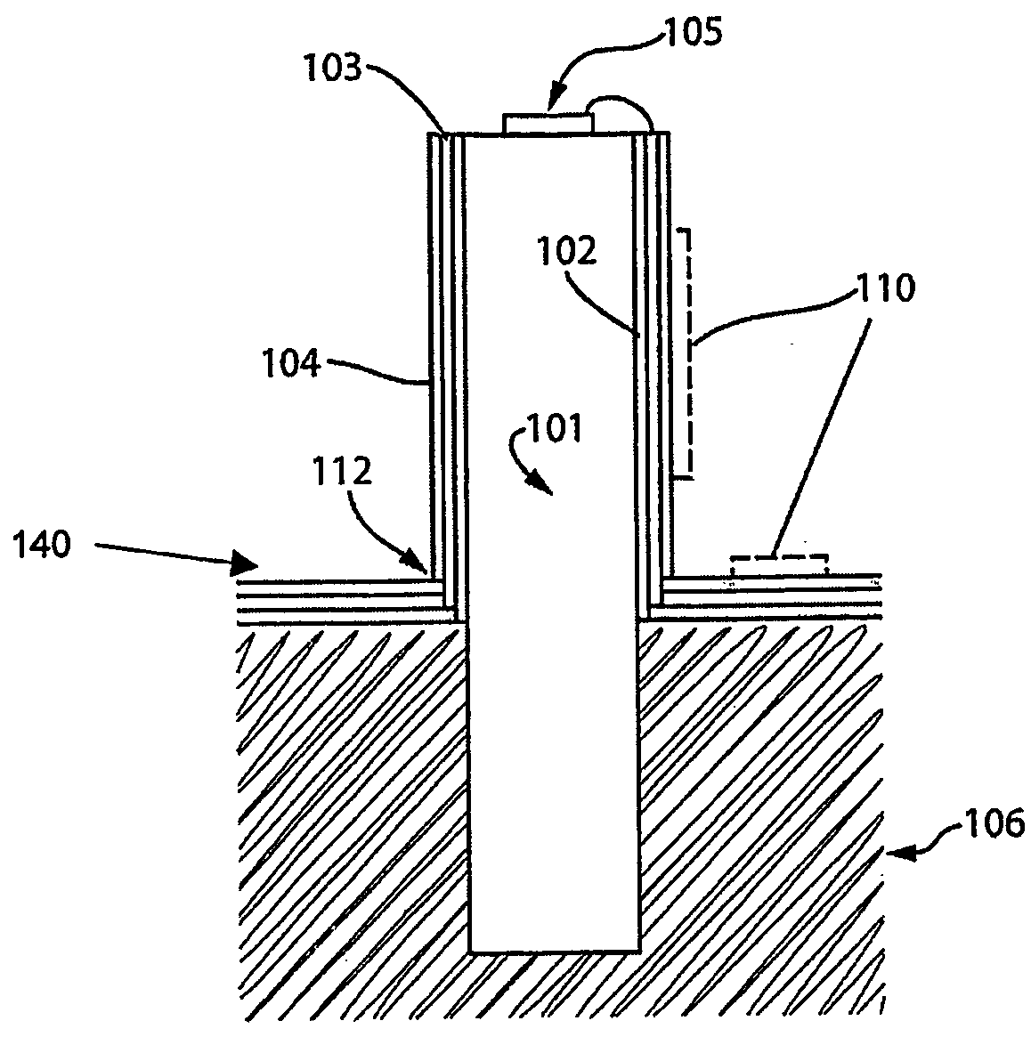
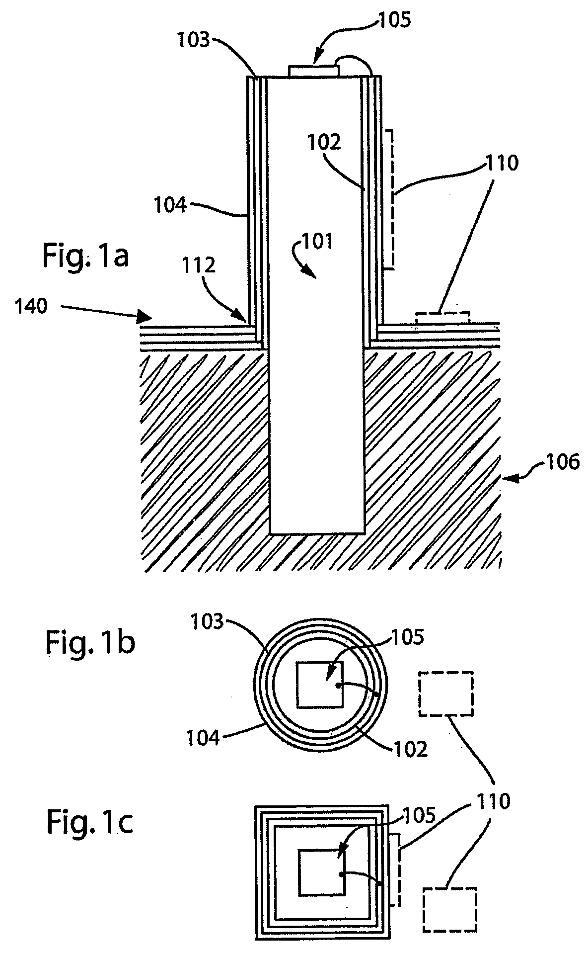
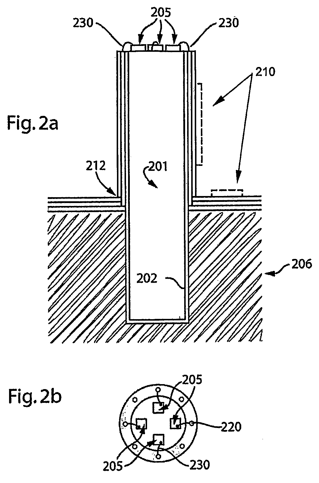
[0015]An object of the present invention is to provide a thermally and electrically conductive apparatus. In accordance with one aspect of the present invention there is provided a thermally and electrically conductive apparatus to which one or more electronic devices can be operatively connected, the apparatus comprising: a thermally conductive element in thermal contact with the one ...

Problems solved by technology

For electronic devices, a high operating temperature can reduce the lifetime of the devices and their efficacy.
Adequate cooling may not be achieved by mounting high-powered electronic components to standard laminate boards, for example FR4 boards.
This form of board typically does not provide sufficient thermal conductivity to remove heat from high-powered components in order that they can operate within a desired temperature range.
An MCPCB can be effective because it can be provide close proximity between heat-producing electrical components and the thermally conductive material, however, the thermal properties of such modified PCB boards are typically insufficient for many of today's applications.
However, these devices are typically designed to be in contact with met...

Method used


Image

  • Thermally and Electrically Conductive Apparatus
  • Thermally and Electrically Conductive Apparatus
  • Thermally and Electrically Conductive Apparatus

Examples


Embodiment Construction

Definitions

[0036]The term “electronic device” is used to define any device wherein its level of operation is dependent on the current being supplied thereto. An electronic device comprises light-emitting elements, laser diodes and any other devices requiring current regulation as would be readily understood by a worker skilled in the art.

[0037]The term “light-emitting element” is used to define any device that emits radiation in any region or combination of regions of the electromagnetic spectrum for example, the visible region, infrared and / or ultraviolet region, when activated by applying a potential difference across it or passing a current through it, for example. Therefore a light-emitting element can have monochromatic, quasi-monochromatic polychromatic or broadband spectral emission characteristics. Examples of light-emitting elements include semiconductor, organic, or polymer / polymeric light-emitting diodes, optically pumped phosphor coated light-emitting diodes, optically p...


PUM

PropertyMeasurementUnit
Electrical conductivityaaaaaaaaaa
Electrical conductoraaaaaaaaaa
Electric propertiesaaaaaaaaaa

Abstract

The present invention provides a thermally and electrically conductive apparatus that can provide both thermal conductivity and electrical conductivity for one or more electronic devices connected thereto. The apparatus comprises a thermally conductive element that is in thermal contact with one or more electronic devices and optionally in contact with a heat dissipation system. A portion of the thermally conductive element is surrounded by a multilayer coating system comprising two or more layers. The multilayer coating system includes alternating electrically insulating and electrically conductive layers in order to provide paths for the supply of electric current to the one or more electronic devices. A conductive layer of the multilayer coating system may be selectively patterned to connect to one or more electronic devices. In this manner, the combination of an electronic circuit carrier and a thermally conductive element can unify thermal conductivity with the provision of power and/or communication into a single integrated unit for use with electronic devices.

Description

FIELD OF THE INVENTION[0001]The present invention pertains to the field of electronic devices and in particular to thermally conductive circuit carriers for use with electronic devices.BACKGROUND[0002]Effective thermal management is a key factor in ensuring stable electronic device performance over a long lifetime. For electronic devices, a high operating temperature can reduce the lifetime of the devices and their efficacy. In addition, for optoelectronic devices, for example light-emitting diodes (LEDs), the junction temperature thereof can also influence the wavelength of the emitted light. Therefore, effective thermal management of these electronic devices is required.[0003]Adequate cooling may not be achieved by mounting high-powered electronic components to standard laminate boards, for example FR4 boards. This form of board typically does not provide sufficient thermal conductivity to remove heat from high-powered components in order that they can operate within a desired tem...

Claims


Application Information

Patent Timeline
IPC IPC(8): H05K7/20H01L33/64
CPCH01L23/13H01L23/142H01L23/367H01L2224/48227H01L33/647H01L2924/12044F21V29/006H01L25/0753F21V29/71F21V3/10H05K1/0272
Inventor SPEIER, INGO
Owner KONINKLIJKE PHILIPS ELECTRONICS NV
Why Eureka
Try Eureka