Vertically Oriented Tube-Launchable Rotary Wing Aircraft Having Respective Rotors at Opposite Ends of Main Body

a technology of vertical orientation and rotors, which is applied in the field of unmanned vehicles, can solve the problems of inefficient use of space by conventional rotary wing craft deployed from tubes, high stall speed of tube-launched fixed-wing aircraft, and inability to hover over a point of interest or maintain position with respect to a slow moving object, etc., to achieve maximum payload volume and weight, and maximize the effect of volum

Active Publication Date: 2018-10-04
UNITED STATES OF AMERICA
View PDF3 Cites 2 Cited by
  • Summary
  • Abstract
  • Description
  • Claims
  • Application Information

AI Technical Summary

Benefits of technology

[0004]Therefore, presented is an expendable rotary wing unmanned aircraft design that may be stored in a cylindrical canister / launcher and launched into flight on command in seconds. Exemplary embodiments provide the ability to store a rotary wing aircraft in a space efficient manner for long time periods yet be launched into flight within seconds whenever needed. Exemplary vehicle designs are volume efficient, simple, cost effective, and maximize the payload volume and weight possible for a given size tube. Exemplary embodiments are capable of launch from land, sea, and air platforms. Possible missions for such a vehicle include electronic warfare, military reconnaissance, precision ordinance delivery, law enforcement surveillance, intelligence gathering, precise sensor delivery, hazardous area inspections, environmental monitoring, etc.

Problems solved by technology

Tube launched fixed wing aircraft that achieve a high payload capacity relative to the tube volume have a very high stall speed and cannot hover over a point of interest or maintain position with respect to a slow moving object such as a ship or truck.
Conventional rotary wing craft deployed from tubes do not use space efficiently.

Method used


Image

  • Vertically Oriented Tube-Launchable Rotary Wing Aircraft Having Respective Rotors at Opposite Ends of Main Body
  • Vertically Oriented Tube-Launchable Rotary Wing Aircraft Having Respective Rotors at Opposite Ends of Main Body
  • Vertically Oriented Tube-Launchable Rotary Wing Aircraft Having Respective Rotors at Opposite Ends of Main Body

Examples


Embodiment Construction

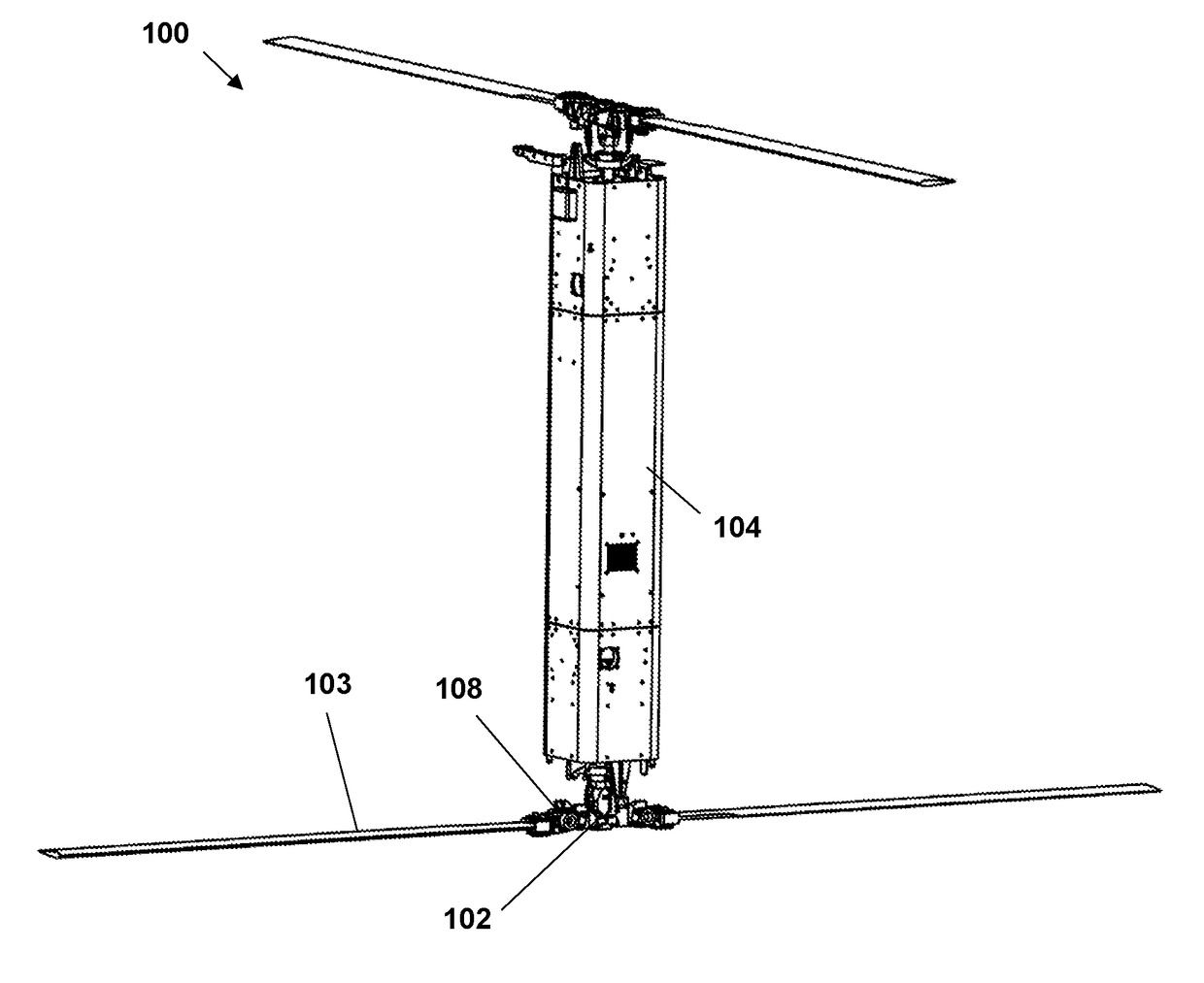
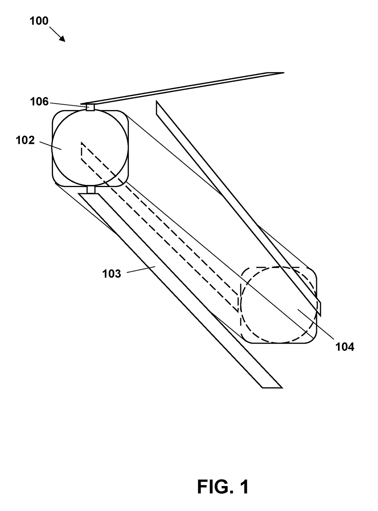
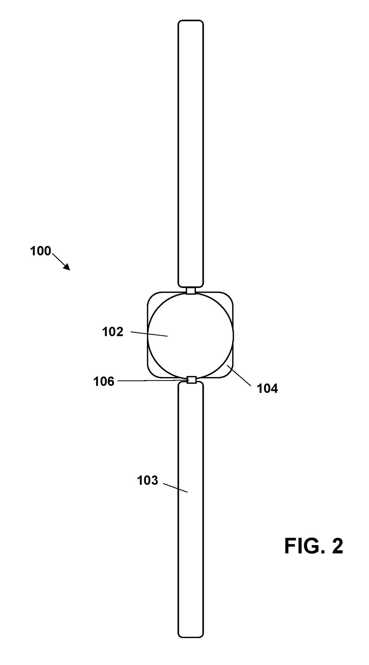
[0029]Shown schematically in isometric view in FIG. 1, top view in FIG. 2, and side view in FIG. 3, an exemplary rotary wing aircraft 100 include counter-rotating coaxial rotors 102—each having, preferably, two blades 103—located at opposite ends of a, preferably square (more preferably square with rounded corners), fuselage / body 104 that fold at hinged joints 106 along the length of the body to efficiently fit in a round tube. Torsion springs 108, shown in FIG. 4, located at the folding pivot help pull the blades when launched out of the tube. The blades can be held in place by the tube or with a servo mechanism (not shown) if desired to be able to keep the blades stowed after exiting the tube. The rotor system at each end of the aircraft is nearly identical with its own electric motor, transmission, swashplate, control servos, rotor hub and blades. The design minimizes the number of unique components which helps reduce cost. The center module is designed to contain the propulsion ...


PUM


Abstract

An expendable rotary wing unmanned aircraft capable of storage in a cylindrical housing includes a longitudinally extending body having an upper end and a lower end; and a pair of counter-rotating coaxial rotors each located at respective ends of longitudinally-extending body, wherein each rotor includes two or more blades, each blade rotatably coupled to a remainder of the rotor at a hinged joint and thereby extending along a length of the body in a storage configuration and extending radially outward from the body in a flight configuration.

Description

RELATED APPLICATIONS[0001]This application claims the benefit of U.S. Provisional Application No. 62 / 479,069 filed Mar. 30, 2017, which is hereby incorporated herein by reference.FIELD OF INVENTION[0002]The present invention relates generally to unmanned vehicles, and more particularly to an unmanned rotary wing vehicle capable of launch from a tube.BACKGROUND[0003]There have been many fixed wing unmanned aircraft designs that are tube launched but relatively few rotary wing aircraft. Tube launched fixed wing aircraft that achieve a high payload capacity relative to the tube volume have a very high stall speed and cannot hover over a point of interest or maintain position with respect to a slow moving object such as a ship or truck. Conventional rotary wing craft deployed from tubes do not use space efficiently.SUMMARY OF INVENTION[0004]Therefore, presented is an expendable rotary wing unmanned aircraft design that may be stored in a cylindrical canister / launcher and launched into f...

Claims


Application Information

Patent Timeline
Patent Type & Authority Applications(United States)
IPC IPC(8): B64C27/50B64C27/10B64C39/02
CPCB64C27/50B64C27/10B64C39/024B64C2201/024B64C2201/08B64C2201/108B64C2201/126B64C2201/18B64C2201/201B64C2201/042B64U70/00B64U10/10B64U30/20B64U2101/00B64U80/70B64U50/19
Inventor TAYMAN, STEVEN K.
Owner UNITED STATES OF AMERICA
Why Eureka
Try Eureka