Head mounted display and method for maneuvering unmanned vehicle

a technology of unmanned vehicles and displays, which is applied in vehicle position/course/altitude control, process and machine control, instruments, etc., can solve the problems of increasing the error in position information, affecting the accuracy of gnss information, and unable to travel to the destination in some cases with accuracy. , to achieve the effect of higher accuracy

Active Publication Date: 2018-10-04
SEIKO EPSON CORP
View PDF3 Cites 11 Cited by
  • Summary
  • Abstract
  • Description
  • Claims
  • Application Information

AI Technical Summary

Benefits of technology

[0008]In the aspect described above, the head mounted display may further include a radio wave receiver that receives a radio wave sent from the unmanned vehicle, and the specific navigation mode may be a mode in which intensity of the radio wave received by the radio wave receiver is measured and a travel route is specified from a change in the measured intensity. Since the navigation mode based on the intensity of the radio wave allows high-accuracy navigation, the display in the aspect with the configuration described above allows travel to the destination with accuracy.
[0009]In the aspect described above, the unmanned vehicle may include an inertial sensor that detects motion of an airframe and successively accumulate a detection value from the inertial sensor to determine a position of the airframe, and the specific navigation mode may be a mode in which the head mounted display acquires the position of the airframe determined by the unmanned vehicle and a travel route is specified from the acquired position of the airframe. The display in the aspect with the configuration described above allows the travel to the destination with accuracy.
[0010]In the aspect described above, the inertial sensor may be a first inertial sensor, the head mounted display may further include a second inertial sensor that detects motion, and the specific navigation mode may be a mode in which the head mounted display successively accumulates a detection value from the second inertial sensor to determine a position of the head mounted display and the travel route is specified from the determined position of the head mounted display and the acquired position of the airframe. According to the aspect with the configuration described above, the unmanned vehicle can home to the head mounted display with higher accuracy.

Problems solved by technology

However, since the position information contained in the GNSS information has a relatively large error of several to several tens of meters, the unmanned aircraft of related art cannot travel to the destination with accuracy in some cases.
The error in the position information increases, for example, in a mountainous area, an intermontane area, and an area between buildings, and the unmanned aircraft therefore undesirably reaches a point far away from the destination in some cases.

Method used


Image

  • Head mounted display and method for maneuvering unmanned vehicle
  • Head mounted display and method for maneuvering unmanned vehicle
  • Head mounted display and method for maneuvering unmanned vehicle

Examples


first embodiment

A. First Embodiment

A-1. Overall Configuration:

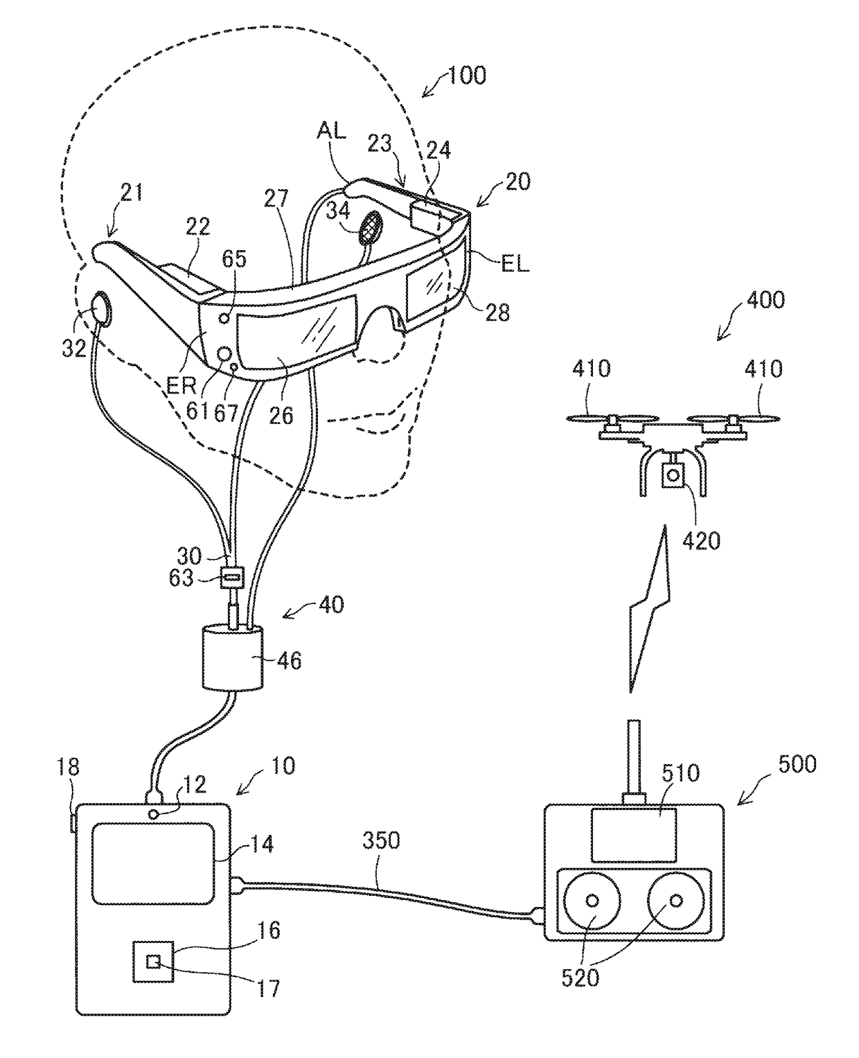
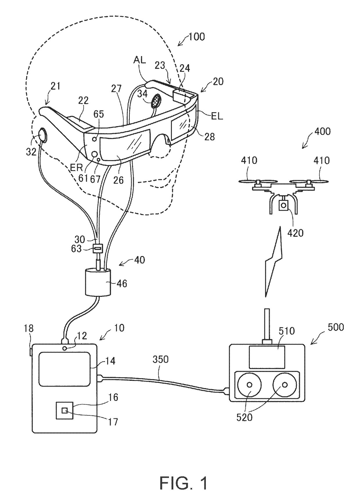
[0057]FIG. 1 is a descriptive diagram showing a schematic configuration of an unmanned aircraft system including a head mounted display in a first embodiment. The unmanned aircraft system includes a head mounted display 100, an unmanned aircraft 400, and a remote control apparatus 500.

[0058]The unmanned aircraft 400 incorporates a GNSS (global navigation satellite system) receiver, an IMU (inertial measurement unit) sensor, and other components and can fly with unmanned aircraft 400 grasping the attitude and position of the airframe with the GNSS receiver, the IMU sensor, and the other components. The unmanned aircraft 400 is what is called a drone. The remote control apparatus 500 is an apparatus that remotely maneuvers the unmanned aircraft 400. The unmanned aircraft 400, which is remotely maneuvered with the remote control apparatus 500, is also capable of autonomous flight. The headmounted display 100 is connected to the remote contr...

second embodiment

B. Second Embodiment

[0155]FIG. 12 is a flowchart showing the homing process carried out by an HMD according to a second embodiment. The homing process carried out by the HMD according to the second embodiment differs from the homing process in the first embodiment (FIG. 9) in terms of the process in S260 corresponding to S160, and the processes in the other steps in the second embodiment are the same as those in the first embodiment. The hardware configuration of the HMD according to the second embodiment is the same as the hardware configuration of the HMD 100 according to the first embodiment. In the following description, the same parts as those in the first embodiment have the same reference characters in the first embodiment.

[0156]In step S260 in the homing process in FIG. 12, the main processor 140 instructs the unmanned aircraft 400 to terminate the travel in the automatic navigation mode but travel in a dead reckoning navigation mode. That is, in the case where the unmanned ...

third embodiment

C. Third Embodiment

[0162]FIG. 13 is a flowchart showing the homing process carried out by an HMD according to a third embodiment. The homing process carried out by the HMD according to the third embodiment differs from the homing process in the first embodiment (FIG. 9) in terms of the process in S360 corresponding to S160, and the processes in the other steps in the third embodiment are the same as those in the first embodiment. The hardware configuration of the HMD according to the third embodiment is the same as the hardware configuration of the HMD according to the first embodiment. In the following description, the same parts as those in the first embodiment have the same reference characters in the first embodiment.

[0163]In step S360 in the homing process in FIG. 13, the main processor 140 instructs the unmanned aircraft 400 to terminate the travel in the automatic navigation mode but travel in a manual navigation mode. That is, in the case where the unmanned aircraft 400 ente...


PUM


Abstract

A head mounted display capable of controlling maneuver of an unmanned vehicle, the head mounted display including a display section that allows visual recognition of an outside scene, a GNSS information acquisition section that acquires a GNSS information, a communication section capable of performing communication using wireless communication with the unmanned vehicle, and a control section, wherein the control section evaluates whether or not the unmanned vehicle has entered a visual field visually recognizable through the display section in a case where the unmanned vehicle travels in an automatic navigation mode in which the unmanned vehicle moves toward a position indicated by the GNSS information and causes the unmanned vehicle to terminate the travel in the automatic navigation mode but travel in a specific navigation mode different from the automatic navigation mode in a case where the control section determines that the unmanned vehicle has entered the visual field.

Description

BACKGROUND1. Technical Field[0001]The present disclosure relates to maneuvering an unmanned vehicle by using a head mounted display.2. Related Art[0002]In recent years, development of an unmanned aircraft called a drone capable of remote maneuver or autonomous flight has been advancing. An unmanned aircraft of related art, for example, incorporates a GNSS receiver, which receives a GNSS electric wave to acquire GNSS information, as described in JP-A-2008-304260. The unmanned aircraft can estimate the attitude and position of the airframe based on the GNSS information. The unmanned aircraft can be maneuvered with not only a dedicated remote control apparatus but a smartphone, a tablet, and other apparatuses.[0003]It is conceivable to cause the unmanned aircraft to automatically travel to a destination by using the GNSS information. However, since the position information contained in the GNSS information has a relatively large error of several to several tens of meters, the unmanned ...

Claims


Application Information

Patent Timeline
Patent Type & Authority Applications(United States)
IPC IPC(8): B64C39/02G05D1/10G02B27/01G06F3/01G01S19/39
CPCB64C39/024G05D1/101G02B27/0172G06F3/011G01S19/39G02B2027/0178G05D1/0088G01S19/49G02B27/017G02B2027/0141G02B2027/0138G05D1/0016G05D1/0033G01S19/14B64U2201/00
Inventor ARUGA, NAOTOMORI
Owner SEIKO EPSON CORP
Why Eureka
Try Eureka