Fluorescent light source device

a technology of fluorescent light source and light source plate, which is applied in the direction of semiconductor lasers, lighting and heating apparatus, instruments, etc., can solve the problems of light source device, difficulty in highly efficient outputting fluorescent light, and difficulty in reducing the size of the device, so as to achieve the effect of reducing the occurrence of temperature quenching in the fluorescent plate, simple structure and reduced design freedom

Active Publication Date: 2018-10-04
USHIO DENKI KK
View PDF0 Cites 1 Cited by
  • Summary
  • Abstract
  • Description
  • Claims
  • Application Information

AI Technical Summary

Benefits of technology

[0023]In the fluorescent light source device of the present invention, the excitation light incident optical system, which causes the excitation light output from each of a plurality of excitation light sources to be incident into the fluorescent light output surface of the fluorescent plate, includes a mirror member having the plurality of excitation light reflection surfaces that convert reflected excitation light into divergent light. Therefore, even when an optical system with the feature of condensing excitation light from the mirror member is disposed between the fluorescent plate and the mirror member so that the focal point is located on the front surface of the fluorescent plate, excitation light output from the plurality of excitation light sources is not excessively condensed on the fluorescent light output surface of the fluorescent plate. Consequently, as a local increase in the temperature of the fluorescent plate is restrained, occurrence of temperature quenching in the fluorescent plate is restrained. Also, a greater degree of design freedom can be afforded in terms of locations where a plurality of excitation light sources are disposed and an excitation light incident optical system. Accordingly, the light source portion constituted by the plurality of excitation light sources and the excitation light incident optical system can be readily made compact.
[0024]Therefore, the fluorescent light source device of the present invention may be configured as a compact device with a simple structure that can highly efficiently emit fluorescent light. Also, an optical system with the feature of condensing excitation light from the mirror member and the feature of converting light output from the fluorescent plate into collimated light can be disposed between the mirror member and the fluorescent plate so that the focal point is located on the front surface of the fluorescent plate. When the fluorescent light source device of the present invention is used for a projector apparatus, high utilization efficiency of fluorescent light can be achieved.

Problems solved by technology

The problem is that it is difficult to reduce the size of the device due to its complicated structure.
However, it has been found that such a fluorescent light source device have the following problems:
Temperature quenching thereby occurs to the fluorescent material in the fluorescent plate, which creates difficulty in highly efficiently outputting fluorescent light.
In addition, when excitation light is excessively condensed on the fluorescent plate and the fluorescent plate is irradiated therewith, the fluorescent plate deteriorates quickly, and the service life thereof is shortened.
Also, when the focal position of the optical system is moved with respect to the fluorescent plate in the optical axis direction in order to prevent excitation light from being excessively condensed on the fluorescent plate, it is difficult for the optical system to adequately convert fluorescent light output from the fluorescent plate into collimated light.
Accordingly, when used as a light source device of a projector apparatus, fluorescent light is not adequately incorporated into a spatial modulating element of the projector apparatus, such as a DMD (Digital Mirror Device).
Consequently, achievement of high light utilization efficiency is difficult.

Method used


Image

  • Fluorescent light source device
  • Fluorescent light source device
  • Fluorescent light source device

Examples


Embodiment Construction

[0034]Hereinbelow, embodiments of a fluorescent light source device of the present invention will be described.

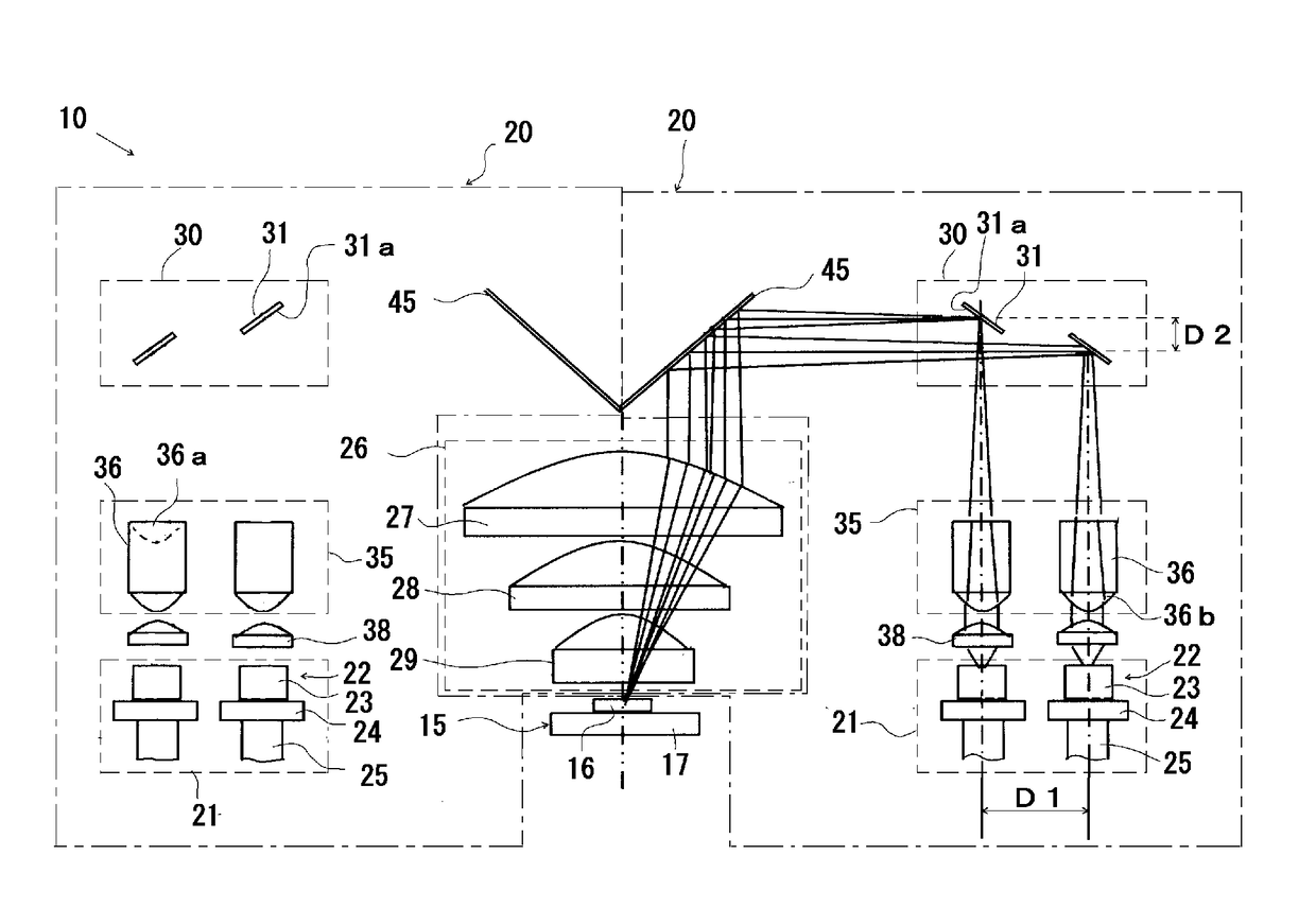
[0035]FIG. 1 is an explanatory view illustrating a summary of one example configuration of the fluorescent light source device of the present invention.

[0036]This fluorescent light source device 10 includes: two excitation light irradiation mechanisms 20; and a fluorescent light-emitting member 15 having a fluorescent plate 16 that receives excitation light from these two excitation light irradiation mechanisms 20 and emits fluorescent light. Each of the two excitation light irradiation mechanisms 20 includes a light source portion 21 including a plurality of (two in the example of the drawing) excitation light sources 22; and an excitation light incident optical system for causing excitation light from this light source portion 21 to be incident into the front surface (upper surface in FIG. 1) of the fluorescent plate 16. The two excitation light irradiation mechanisms 20 ...


PUM


Abstract

Disclosed is the provision of a fluorescent light source device that can highly efficiently emit fluorescent light and can be configured as a compact device with a simple structure. Further disclosed is the provision of a fluorescent light source device that can achieve high utilization efficiency of fluorescent light when it is utilized in a projector apparatus. A fluorescent light source device of the present invention includes: a plurality of excitation light sources for outputting excitation light; a fluorescent plate for receiving the excitation light and emitting fluorescent light; and an excitation light incident optical system for causing excitation light from each of the plurality of excitation light sources to be incident into a fluorescent light output surface of the fluorescent plate, wherein the excitation light incident optical system includes a mirror member having a plurality of excitation light reflection surfaces for changing respective travel directions of the excitation light output from the respective excitation light sources, and the excitation light reflected by the plurality of excitation light reflection surfaces is divergent light.

Description

TECHNICAL FIELD[0001]The present invention relates to a fluorescent light source device. More specifically, the present invention relates to a fluorescent light source device that can be preferably used as, for example, a light source device for a projector apparatus.BACKGROUND ART[0002]In recent years, a fluorescent light source device has been proposed as a light source device for a projector apparatus (see, for example, Patent Literature 1). The proposed fluorescent light source device has: an excitation light source including a solid light-emitting element, such as a laser diode; and a fluorescent plate that receives excitation light from this excitation light source and outputs fluorescent light.[0003]For example, Patent Literature 1 discloses a fluorescent light source device including: an excitation light-emitting portion whereby excitation light from the excitation light source is converted into and output as collimated light; a transmission-type fluorescent plate that recei...

Claims


Application Information

Patent Timeline
Patent Type & Authority Applications(United States)
IPC IPC(8): F21S2/00F21V5/04F21V7/09F21V7/24F21V9/35G02B19/00G03B21/20
CPCF21S2/00F21V5/04F21V7/09F21V7/24F21V9/35G02B19/0019G03B21/204F21V5/008F21V7/22F21V13/00F21V9/30G02B19/0014G03B21/2013H01S5/0071H01S5/4012H01S5/0087
Inventor INOUE, MASAKIOSAWA, OSAMU
Owner USHIO DENKI KK
Why Eureka
Try Eureka