

Underwater image capturing apparatus
an image capture and underwater technology, applied in underwater equipment, underwater special purpose vessels, instruments, etc., can solve the problems of expensive and difficult acquisition of miniature unmanned aerial vehicles (uavs) typified by unmanned helicopters for industrial use, and achieve the effect of easy control of image capture position and direction in water and flexibility
- Summary
- Abstract
- Description
- Claims
- Application Information
AI Technical Summary
Benefits of technology
Problems solved by technology
Method used
Image

Examples
first embodiment
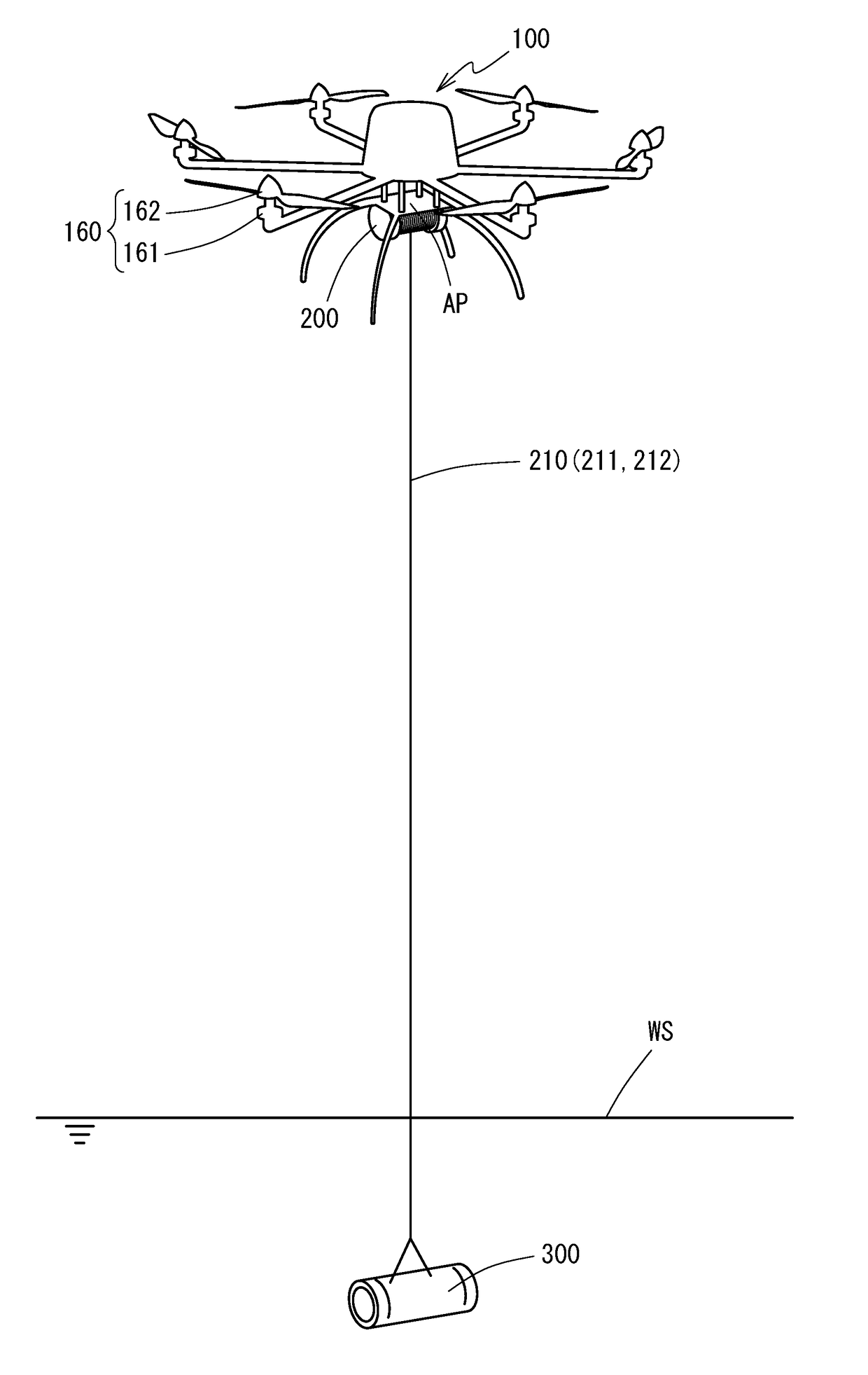
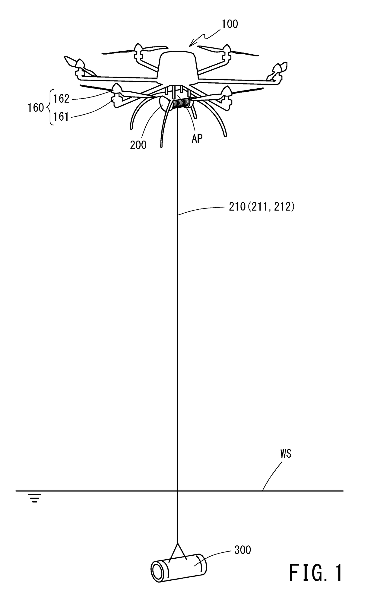
[0053]FIG. 1 is a schematic diagram depicting an appearance in which an underwater image capturing apparatus 91 pertaining to a first embodiment of the present invention captures images in water. The underwater image capturing apparatus 91 is comprised mainly of a multicopter 100 (a miniature unmanned aerial vehicle) equipped with a plurality of rotors 160 (rotary wings), a winch 200 (a winding machine) fixed to an adapter plate AP of the multicopter 100, an underwater camera 300 capable of capturing images in water. Now, a “rotor” termed in the present invention means a motor 161 with a blade 162 installed thereon.
[0054]The multicopter 100 according to the present embodiment is a hexacopter equipped with six rotors 160. The number of the rotors 160 of the multicopter 100 is not limited to six, and the multicopter may be configured to be a tricopter (with three rotors), a quadcopter (with four rotors), or an octocopter (with eight rotors) depending on required flight performance, re...
second embodiment
[0070]Descriptions are provided below about a second embodiment of the underwater image capturing apparatus pertaining to the present invention. FIG. 3 is a schematic diagram depicting an appearance in which an underwater image capturing apparatus 92 pertaining to the second embodiment captures images in water. FIG. 4 is a block diagram depicting a functional configuration of the underwater image capturing apparatus 92. Now, in the following description, a component having a similar or the same function as in the foregoing embodiment is assigned the same reference designator as in the foregoing embodiment and its detailed description is omitted.
[0071]An underwater camera 400 according to the second embodiment is comprised mainly of a camera module 410 which captures images in water, a plurality of screw propellers 470 which allows the underwater camera 400 to change its orientation in water, a control device 430 which integrally manages operation of the respective screw propellers 4...
third embodiment
[0079]Descriptions are provided below about a third embodiment of the underwater image capturing apparatus pertaining to the present invention. FIG. 5 is a schematic diagram depicting an appearance in which an underwater image capturing apparatus 93 pertaining to the third embodiment captures images in water. Now, the underwater image capturing apparatus 93 has the same functional configuration as that of the image capturing apparatus 91 of the first embodiment (FIG. 2). Now, in the following description, a component having a similar or the same function as in the foregoing embodiments is assigned the same reference designator as in the foregoing embodiments and its detailed description is omitted.
[0080]The winch 200 in the present embodiment is capable of delivering and winding two wires 210 at the same time and these two wires 210 are connected to an upper surface of the underwater camera 30 with a given interval therebetween. Thereby, when the multicopter 100 yaws and these wires...
PUM
 Abstract
Description
Claims
Application Information