Sewage treatment system

a technology for sewage treatment and sewage, which is applied in the direction of water/sludge/sewage treatment, sewer pipelines, sewerage structures, etc., can solve the problems of inability to function of septic tanks and high cost of manufacture and installation of such configurations, and achieves less anaerobic digestion, convenient digestion, and improved treatment

Active Publication Date: 2018-10-18
WATERLOO BIOFILTER SYST INC
View PDF0 Cites 0 Cited by
  • Summary
  • Abstract
  • Description
  • Claims
  • Application Information

AI Technical Summary

Benefits of technology

[0006]As set out herein, in accordance with this disclosure, raw sewage may be fed directly into a small diameter treatment pipe which is located inside a typical septic tank and empties into the septic tank without the need for a solids settling chamber upstream of the inlet of the treatment pipe. An advantage of this design is that a longitudinally extending flow conduit, that may be of any particular cross-sectional shape, such as a thin walled, smaller diameter, flexible pipe, may be inserted into any standard box-like tank. Accordingly, waste may be delivered to a septic tank whereupon the waste enters the flow conduit and passes through the flow conduit prior to entering the volume defined by the wall of the septic tank (i.e., the portion of the septic tank exterior to the flow conduit contained therein). Accordingly, the waste travels through the flow conduit prior to entering the open volume of the septic tank. During the passage of solid waste such as toilet paper, fecal matter, etc. through the flow conduit, the solid waste is partially digested and therefore less anaerobic digestion is required in the portion of the septic tank exterior to the flow conduit contained therein. Without being bound by theory, it is believed that as sewage solids and dissolved contaminants are digested, the microbial ...

Problems solved by technology

However, as tanks are typically box-like and blocky shaped without flow-directing baffles, septic tanks do not function as true anaerobic digesters that promote fermentati...

Method used


Image

  • Sewage treatment system
  • Sewage treatment system
  • Sewage treatment system

Examples


examples

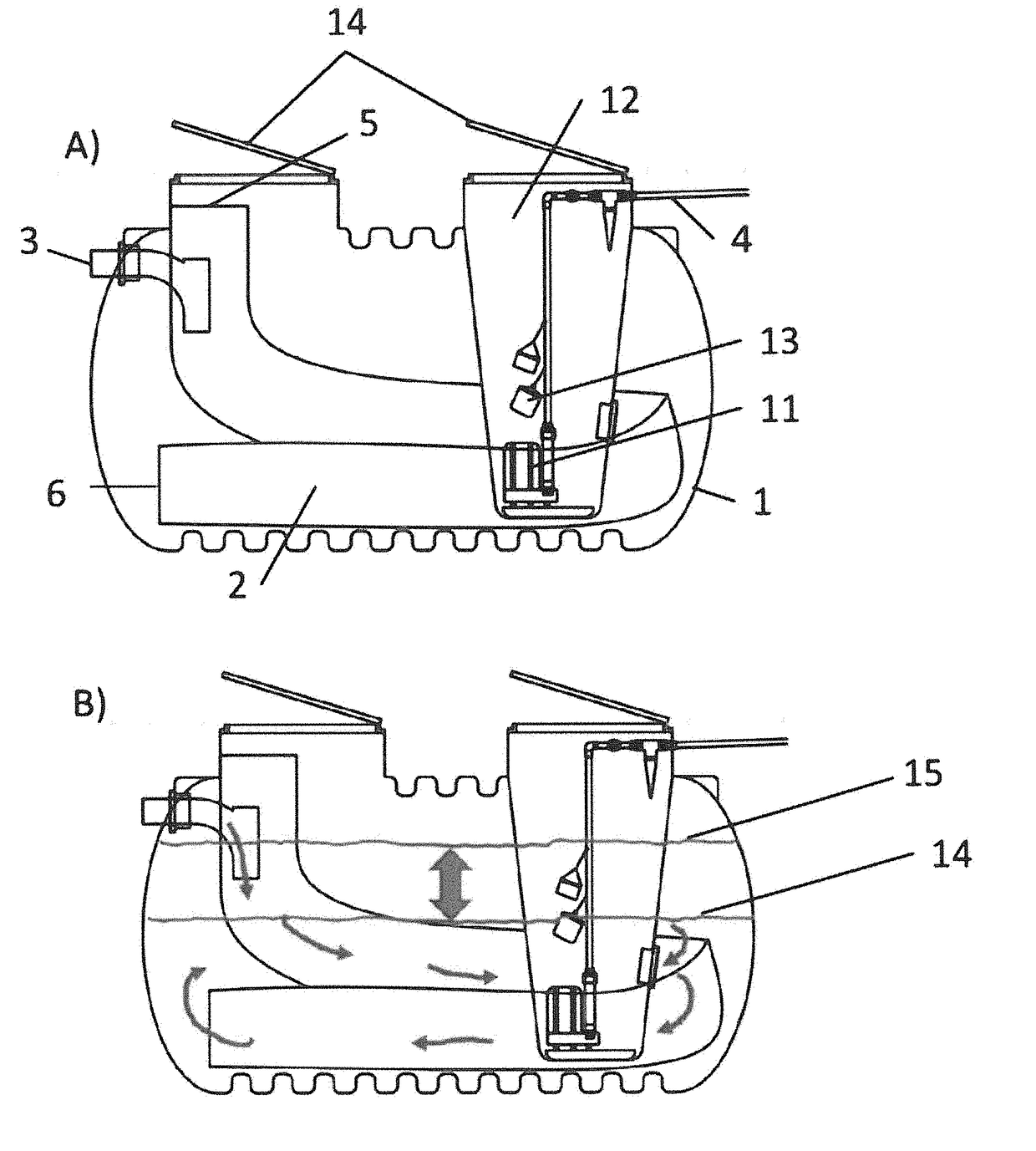
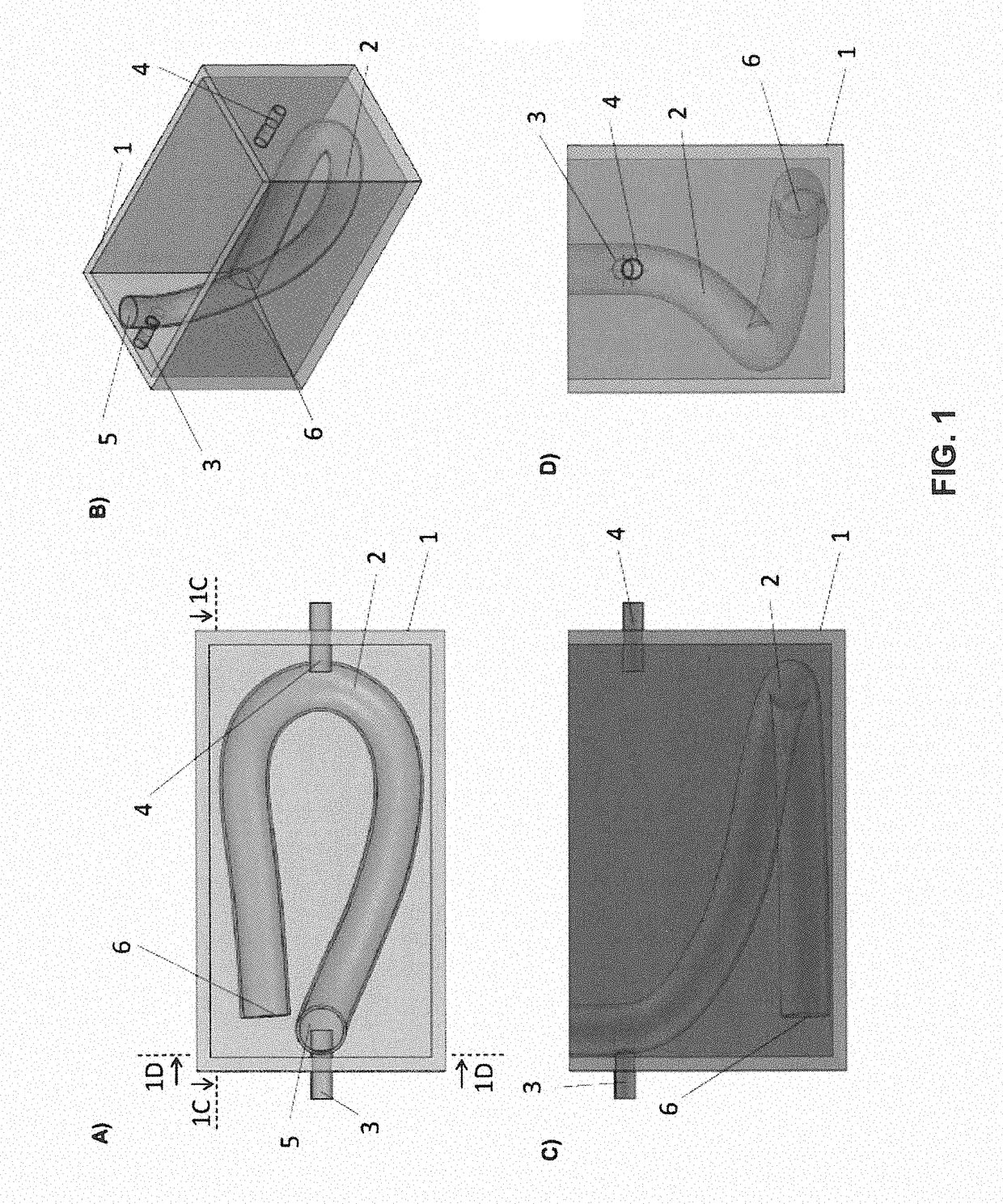
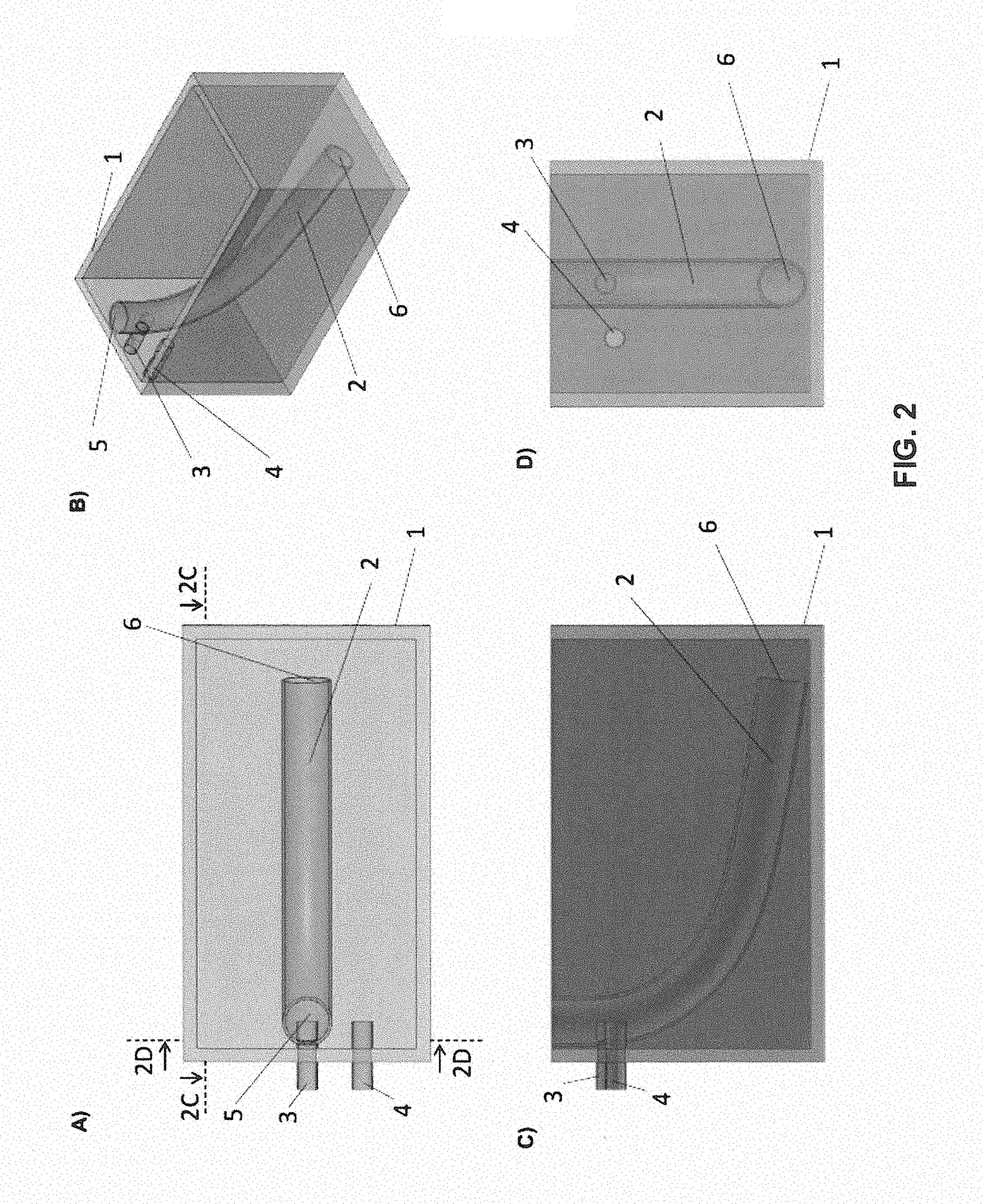
[0089]Testing shows that an “InnerTube digester” comprising septic tank with a pipe positioned within can receive raw sewage directly without going through an initial sump chamber or larger tank without clogging. Improved treatment results over conventional septic tanks are seen, especially with respect to total suspended solids (TSS) removal and solids accumulation, with a reasonable improvement in carbonaceous biochemical oxygen demand (cBOD) removal as well.

(1) Comparative Performance at BNQ Test Facility

[0090]Side by side testing at the Bureau de Normalisation de Quebec (BNQ) test facility in Quebec Canada showed that the InnerTube digester performed substantially better in solids digestion than a standard septic tank of the same size and same sewage flow of 1500 L / day.

[0091]A 750 US gallon Roth brand septic tank and an InnerTube digester were installed side by side in parallel with sewage flow of 1500 L / day delivered to each tank. The Digester tank contained 15′ of 12″ diam...


PUM


Abstract

A septic system, including a septic tank and a pipe positioned within the septic tank, is provided. The pipe receives sewage and provides a flooded, anaerobic environment for sewage passing therethrough. The outlet of the pipe is positioned inside the septic tank and is optionally spaced from the outlet of the septic tank. In operation, the sewage introduced into the pipe generally separates into a solid portion comprising sludge, which remains in the pipe, and a liquid portion, which passes through and around the sludge. In one embodiment, the septic system has an absence of a sump chamber upstream of the septic tank.

Description

FIELD[0001]This disclosure relates to systems for treating sewage and other organic wastewaters; and more specifically to septic systems.INTRODUCTION[0002]Anaerobic treatment tanks, also known as septic tanks, are designed to receive sewage. Solids settle or float within the tank, and scum forms at the surface. Some of the settled solids are anaerobically digested, and any remaining solids are pumped out on a regular basis. However, as tanks are typically box-like and blocky shaped without flow-directing baffles, septic tanks do not function as true anaerobic digesters that promote fermentation and hydrolysis reactions for substantially all of the solid waste that enters the septic tank. “True digesters” are designed so that flow is directed to minimize hydraulically stagnant zones, and this directional flow, although slow, produces an improved environment to maximize anaerobic microbial digestion.[0003]“Upflow Anaerobic Sludge Blanket” (UASB) systems are vertical septic tanks with ...

Claims


Application Information

Patent Timeline
IPC IPC(8): C02F3/28E03F3/04E03F11/00
CPCC02F3/2866C02F2103/005E03F11/00E03F3/04C02F1/32C02F3/288C02F3/302C02F2203/006E03F5/18Y02A20/208C02F3/286
Inventor JOWETT, EDWIN CRAIG
Owner WATERLOO BIOFILTER SYST INC
Why Eureka
Try Eureka