Power converter
a converter and power technology, applied in the direction of electric variable regulation, process and machine control, instruments, etc., can solve the problems of difficult difficult to etc., to prevent an energy loss, reduce the number of parts of the converter, and reduce the size and cost of the converter
- Summary
- Abstract
- Description
- Claims
- Application Information
AI Technical Summary
Benefits of technology
Problems solved by technology
Method used
Image

Examples
first embodiment
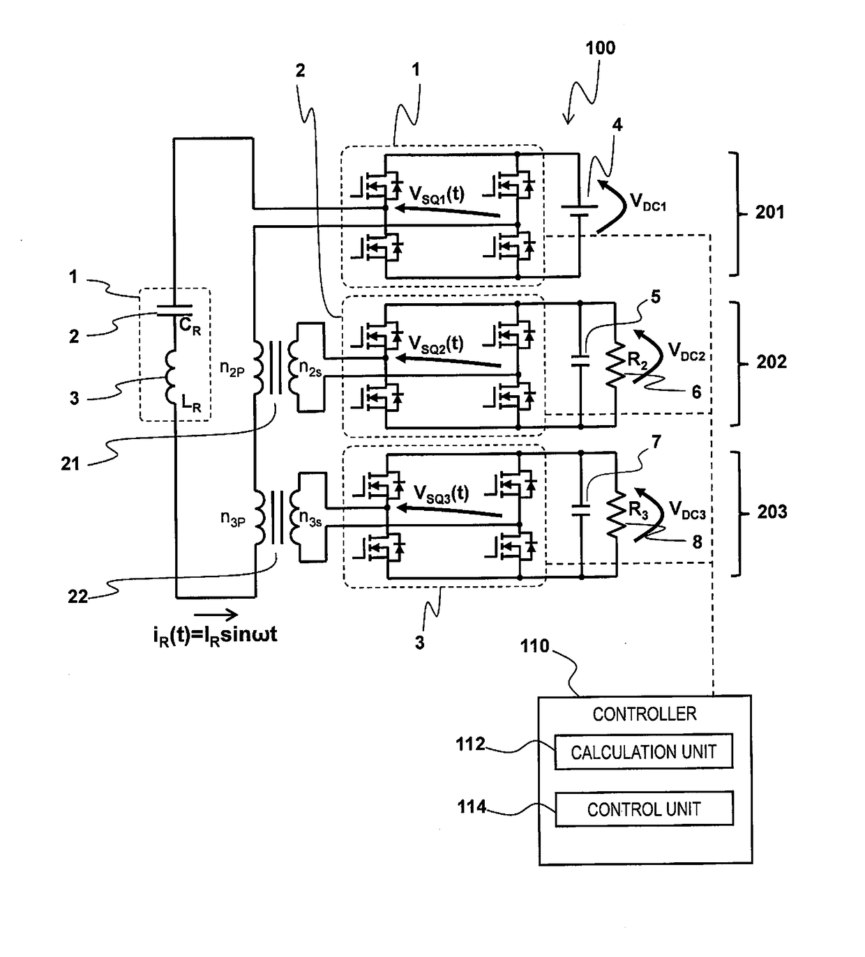
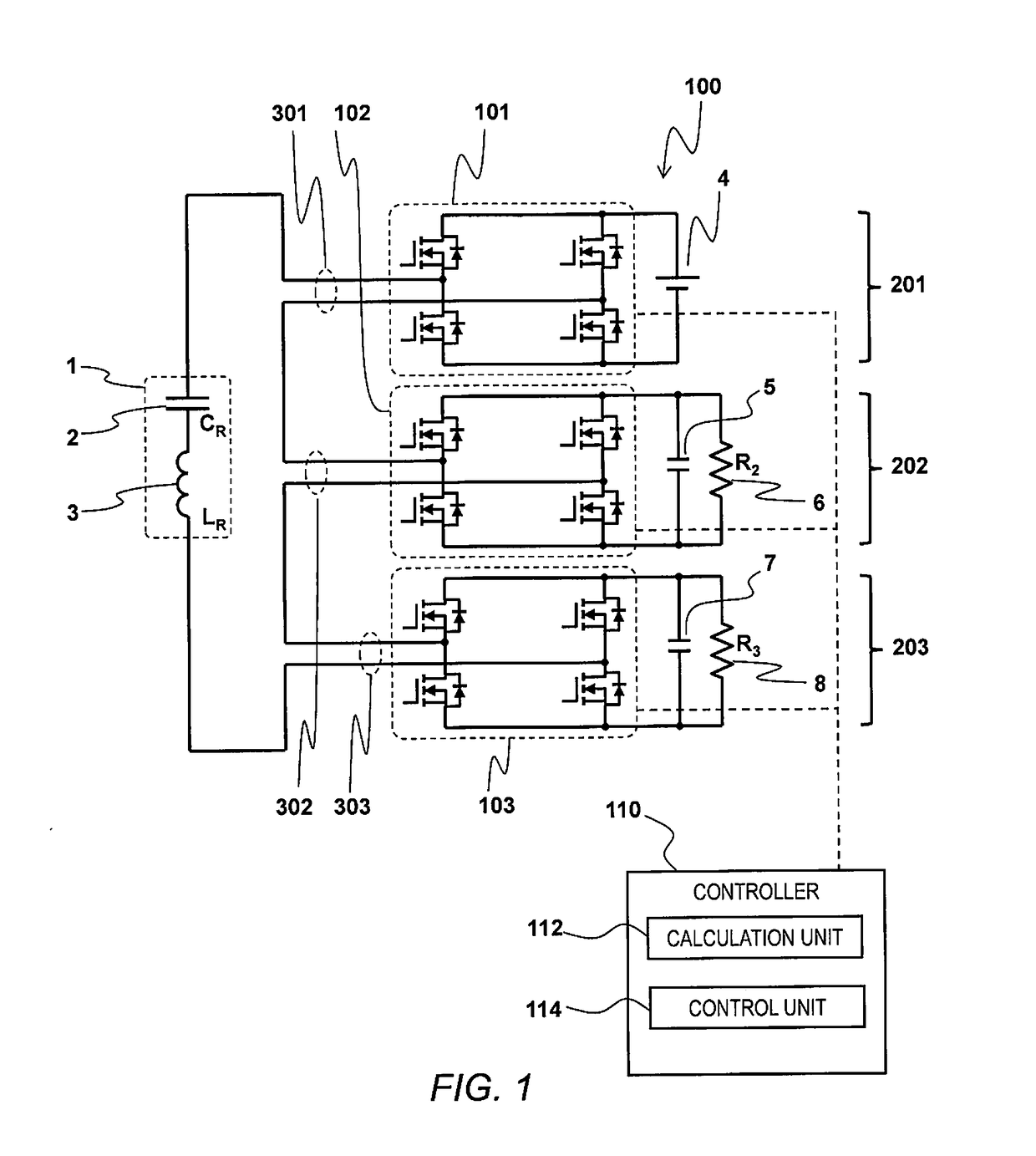
[0052]Referring to FIGS. 1 to 18, and Tables 1 and 2, a power converter 100 is illustrated in accordance with a first embodiment. FIG. 1 is a circuit diagram illustrating a circuit structure of the power converter 100. As shown in FIG. 1, the power converter 100 is the so-called multi-port converter with three ports, such as a first port 201, a second port 202, and a third port 203. The first port 201 includes a first switching circuit 101 and a first power source 4. The second port 202 includes a second switching circuit 102, a second smoothing capacitor 5 and a second load resistance 6. The third port 203 includes a third switching circuit 103, a third smoothing capacitor 7 and a third load resistance 8. As illustrated in FIG. 1, each of the first, second and third switching circuits 101, 102 and 103 includes four switching elements, such as MOSFET or any other elements as needed and / or desired. In the illustrated embodiment, each of the first, second and third switching circuits ...
second embodiment
[0108]FIG. 19 is a circuit diagram illustrating a circuit structure of a power convertor 100 in accordance with the second embodiment. The power convertor 100 illustrated in FIG. 19 is basically identical to the power convertor 100 illustrated in FIG. 1, except that a second power source 9 is connected to the second port 202 instead of the second load resistance 6 illustrated in FIG. 1.
[0109]More specifically, with the power convertor 100 in accordance with the first embodiment, two loads are connected to a single power source. On the other hand, with the power convertor 100 in accordance with the second embodiment, a single load is connected to two power sources. In other words, the power convertor 100 forms a DC-DC convertor with the first and second power sources 4 and 9 as multiple (a pair of) inputs and the third load resistance 8 as a single output.
[0110]With this power convertor 100 in accordance with the second embodiment, as shown in FIG. 19, even if two power sources are p...
third embodiment
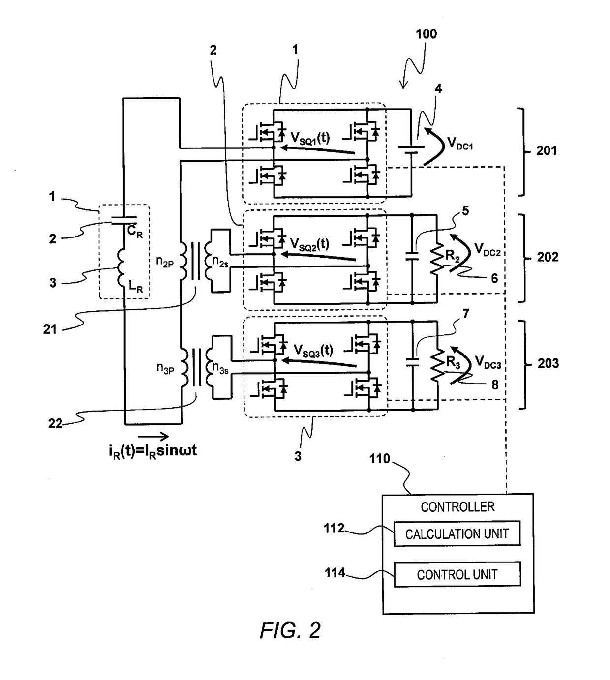
[0111]FIG. 20 is a circuit diagram illustrating a circuit structure of a power convertor 100 in accordance with the third embodiment. The power convertor 100 illustrated in FIG. 20 is basically identical to the power convertor 100 illustrated in FIG. 2, except that a first isolation transformer 23 is inserted at a location where the first port 201 is connected to the series resonant circuit 1.
[0112]More specifically, as shown in FIG. 20, the numbers of turns of the first isolation transformer 23 are n1P and n1S, and the first port 201 is electrically isolated from the closed circuit. With this configuration, each of the first, second and third ports 201, 202 and 203 can be isolated from the series resonant circuit 1, as understood in the art. Also, the power convertor 100 can be operated in the similar manner as explained in the first embodiment, as understood in the art, by taking the numbers of turns of the first isolation transformer 23 into account.
PUM
 Abstract
Description
Claims
Application Information
 - R&D Engineer
- R&D Manager
- IP Professional
- Industry Leading Data Capabilities
- Powerful AI technology
- Patent DNA Extraction
Browse by: Latest US Patents, China's latest patents, Technical Efficacy Thesaurus, Application Domain, Technology Topic.
© 2024 PatSnap. All rights reserved.Legal|Privacy policy|Modern Slavery Act Transparency Statement|Sitemap